Schemi di impianto
NIMBUS COMPACT S NET
3
2
VE
1
6
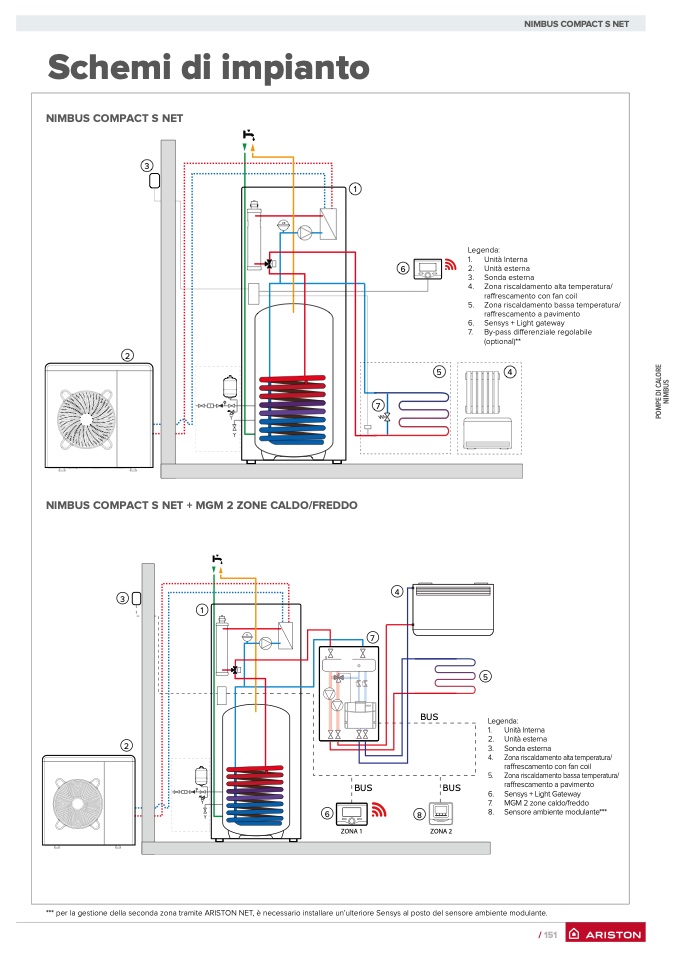
Legenda:
1.
Unità Interna
2. Unità esterna
3. Sonda esterna
4. Zona riscaldamento alta temperatura/
raffrescamento con fan coil
5. Zona riscaldamento bassa temperatura/
raffrescamento a pavimento
6. Sensys + Light gateway
7.
By-pass differenziale regolabile
(optional)**
5
4
NIMBUS COMPACT S NET
P
O
M
P
E
D
I
C
A
L
O
R
E
N
I
M
B
U
S
NIMBUS COMPACT S NET + MGM 2 ZONE CALDO/FREDDO
3
2
1
4
7
BUS
6
8
ZONA 1
VE
*** per la gestione della seconda zona tramite ARISTON NET, è necessario installare un’ulteriore Sensys al posto del sensore ambiente modulante.
7
BUS
Legenda:
1.
Unità Interna
2. Unità esterna
3. Sonda esterna
4.
Zona riscaldamento alta temperatura/
raffrescamento con fan coil
5.
Zona riscaldamento bassa temperatura/
raffrescamento a pavimento
6. Sensys + Light Gateway
7.
MGM 2 zone caldo/freddo
8. Sensore ambiente modulante***
BUS
ZONA 2
5
/ 151

