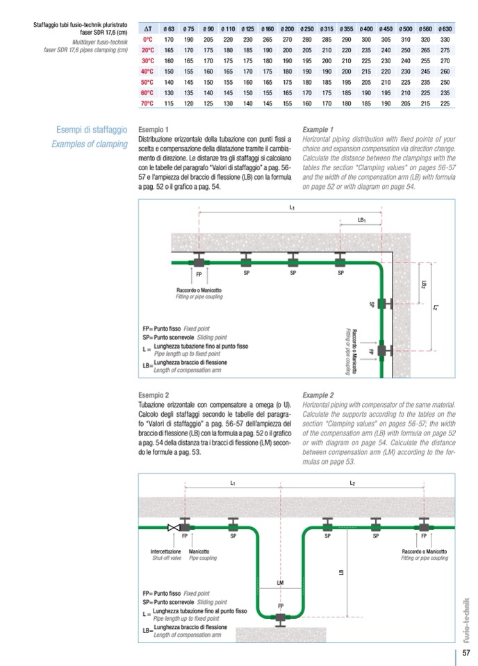
Staffaggio tubi fusio-technik pluristrato
faser SDR 17,6 (cm)
Multilayer fusio-technik
faser SDR 17,6 pipes clamping (cm)
Esempi di staffaggio
Examples of clamping
0°C
30°C
50°C
70°C
Esempio 1
Distribuzione orizzontale della tubazione con punti
fissi a
scelta e compensazione della dilatazione tramite il cambia-
mento di direzione. Le distanze tra gli staffaggi si calcolano
con le tabelle del paragrafo “Valori di staffaggio” a pag. 56-
57 e l’ampiezza del braccio di
flessione (LB) con la formula
apag.52oilgra
ficoapag.54.
330
270
250
225
∆T
20°C
40°C
60°C
Ø 63
170
165
160
150
140
130
115
Ø 75
190
170
165
155
145
135
120
Ø 90
205
175
170
160
150
140
125
Ø 110
220
180
175
165
155
145
130
Ø125
230
185
175
170
160
150
140
Ø160
265
190
180
175
165
155
145
Ø 200
270
200
190
180
175
165
155
Ø 250
280
205
195
190
180
170
160
Ø 315
285
210
200
190
185
175
170
Ø 355
290
220
210
200
195
185
180
Ø 400
300
235
225
215
205
190
185
Ø 450
305
240
230
220
210
195
190
Ø 500
310
250
240
230
225
210
205
Ø 560
320
265
255
245
235
225
215
Ø 630
275
260
235
Example 1
Horizontal piping distribution with fixed points of your
choice and expansion compensation via direction change.
Calculate the distance between the clampings with the
tables the section “Clamping values” on pages 56-57
and the width of the compensation arm (LB) with formula
on page 52 or with diagram on page 54.
FP
Raccordo o Manicotto
Fitting or pipe coupling
SP
SP
SP
FP= Punto fisso Fixed point
SP=Puntoscorrevole Slidingpoint
L =
Lunghezza tubazione fino al punto
fisso
Pipe length up to fixed point
LB=
Lunghezza braccio di
flessione
Length of compensation arm
L1
LB1
L
2
L
B
2
S
P
F
P
R
a
c
c
o
r
d
o
o
M
a
n
i
c
o
t
t
o
F
i
t
t
i
n
g
o
r
p
i
p
e
c
o
u
p
l
i
n
g
Esempio 2
Tubazione orizzontale con compensatore a omega (o U).
Calcolo degli staffaggi secondo le tabelle del paragra-
fo “Valori di staffaggio” a pag. 56-57 dell’ampiezza del
braccio di
flessione (LB) con la formula a pag. 52 o il gra
fico
a pag. 54 della distanza tra i bracci di flessione (LM) secon-
do le formule a pag. 53.
Example 2
Horizontal piping with compensator of the same material.
Calculate the supports according to the tables on the
section “Clamping values” on pages 56-57; the width
of the compensation arm (LB) with formula on page 52
or with diagram on page 54. Calculate the distance
between compensation arm (LM) according to the for-
mulas on page 53.
L1
L2
FP
SP
Intercettazione Manicotto
Shut-off valve Pipe coupling
FP= Punto
fisso Fixed point
SP=Puntoscorrevole Slidingpoint
L =
Lunghezza tubazione
fino al punto
fisso
Pipe length up to fixed point
LB=
Lunghezza braccio di
flessione
SP
SP
FP
Raccordo o Manicotto
Fitting or pipe coupling
Length of compensation arm
LM
FP
L
B
57

