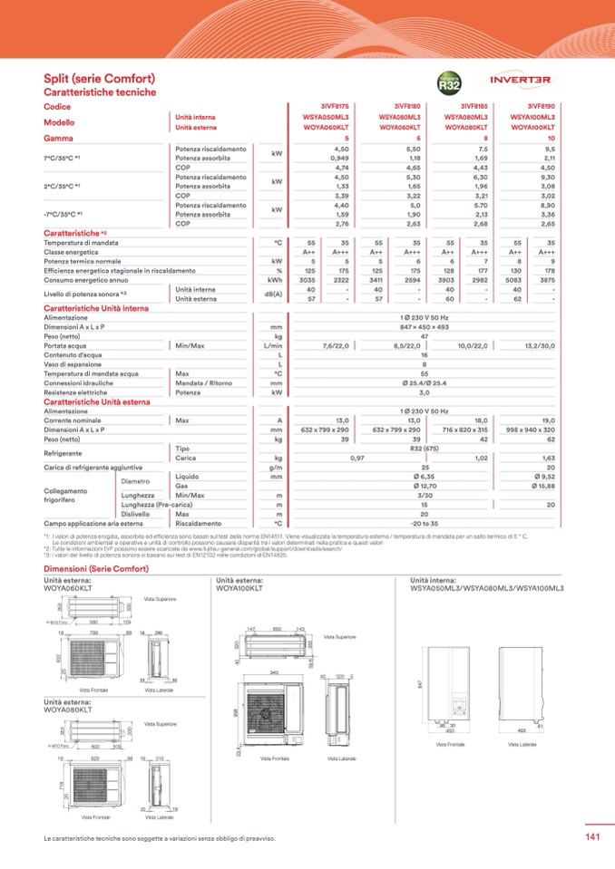
Split (serie Comfort)
Caratteristiche tecniche
Codice
Modello
Gamma
7°C/35°C *1
2°C/35°C *1
-7°C/35°C *1
Caratteristiche *
2
3IVF8175
WSYA050ML3
WOYA060KLT
Refrigerante
R32
3IVF8185
WSYA080ML3
WOYA080KLT
Temperatura di mandata
Classe energetica
Potenzatermicanormale
Efficienza energetica stagionale in riscaldamento
Consumo energetico annuo
kW
kW
kW
°C
kW
%
kWh
dB(A)
4,50
0,949
4,74
4,50
1,33
3,39
4,40
1,59
2,76
55
35
A++
A+++
5
5
125
175
3035
2322
40
-
57
-
7,6/22,0
13,0
632x799x290
39
5,50
1,18
4,65
5,30
1,65
3,22
5,0
1,90
2,63
55
35
A++
A+++
5
6
125
175
3411
2594
40
-
57
-
7.5
1,69
4,43
6,30
1,96
3,21
5.70
2,13
2,68
55
35
A++
A+++
6
7
128
177
3903
2982
40
-
60
-
9,5
2,11
4,50
9,30
3,08
3,02
8,90
3,36
2,65
55
35
A++
A+++
8
9
130
178
5083
3875
40
-
62
-
13,2/30,0
19,0
998x940x320
62
1,63
20
Ø 9,52
Ø 15,88
20
Livello di potenza sonora *3
Caratteristiche Unità interna
Unità interna
Unità esterna
Alimentazione
DimensioniAxLxP
mm
1 Ø 230 V 50 Hz
847×450×493
47
8,5/22,0
10,0/22,0
16
8
55
Ø 25.4/Ø 25.4
3,0
1 Ø 230 V 50 Hz
13,0
18,0
632x799x290
716x820x315
Peso (netto)
Portataacqua
Contenuto d’acqua
Vaso di espansione
Temperatura di mandata acqua
Connessioni idrauliche
Resistenze elettriche
Caratteristiche Unità esterna
Alimentazione
Correntenominale
DimensioniAxLxP
Peso (netto)
kg
Min/Max
L/min
L
L
Max
°C
Mandata / Ritorno
mm
Potenza
kW
Max
A
mm
kg
39
R32 (675)
25
Ø 6,35
Ø 12,70
3/30
15
20
-20 to 35
42
1,02
Tipo
Refrigerante
Carica
kg
Carica di refrigerante aggiuntiva
g/m
Liquido
mm
Diametro
Gas
Collegamento
Lunghezza
Min/Max
m
frigorifero
Lunghezza (Pre-carica)
m
Dislivello
Max
m
Campo applicazione aria esterna
Riscaldamento
°C
0,97
Unità interna
Unità esterna
Potenza riscaldamento
Potenza assorbita
COP
Potenza riscaldamento
Potenza assorbita
COP
Potenza riscaldamento
Potenza assorbita
COP
3IVF8180
WSYA080ML3
WOYA060KLT
5
6
3IVF8190
WSYA100ML3
WOYA100KLT
8
10
*1: I valori di potenza erogata, assorbita ed efficienza sono basati sul test della norma EN14511. Viene visualizzata la temperatura esterna / temperatura di mandata per un salto termico di 5 ° C.
Le condizioni ambientali e operative e unità di controllo possono causare disparità tra i valori determinati nella pratica e questi valori
o
i
*2: Tutte le informazioni ErP possono essere scaricate da www.fujitsu-general.com/global/support/downloads/search/
g
a
f
*3: I valori del livello di potenza sonora si basano sui test di EN12102 nelle condizioni di EN14825.
s
f
a
t
3
5
0
3
o
l
r
e
3
o
i
o
i
3
p
Dimensioni (Serie Comfort)
g
g
e
s
Unità esterna:
4-M10 Foro
a
t
a
t
e
t
o
i
a
f
a
f
s
a
r
580
109
3
3
0
0
r
r
f
s
o
s
o
n
I
g
o
l
i
l
a
Interasse per lo staffaggio
Unità esterna:
Unità interna:
WOYA060KLT
3
3
3
3
p
a
f
p
s
5
5
3
3
g
e
e
f
a
g
t
WOYA100KLT
WSYA050ML3/WSYA080ML3/WSYA100ML3
e
e
s
s
3
0
r
a
s
t
s
o
l
4-M41-0MF1o0roForo
580580
109109
a
r
o
a
r
5
3
e
l
Vista Superiore
5
3
n
n
e
3
0
e
t
r
e
t
3
3
p
3
3
e
I
p
I
s
InteIrnatsesraespserploersltoafsfatagfgfaioggio
19
799
68 16
290
s
e
e
a
r
s
t
4-M10 Foro
580
109
Unit: mm
Unit: mm
4-M10 Foro
VisVtaisStaupSeurpioereiore
580
109
r
e
t
g
g
a
n
I
o
i
o
i
147
650
147
650
143
143
Interasse per lo staffaggio
n
I
g
a
g
a
Unit: mm
19 19
Interasse per lo staffaggio
799799
68 6186 16
3
2
f
f
147
650
143
6
0
2
5
290290
0
5
o
i
o
i
a
t
s
a
t
s
3
3
5
a
a
3
3
0
r
0
r
2
3
5
3
g
g
o
l
o
l
g
g
Vista Superiore
Vista Superiore
2
3
3
a
t
s
a
t
s
3
3
3
p
e
3
p
e
0
0
2
5
f
f
5
5
3
e
3
e
19
799
68 16
290
19
2
2
4
5
5
3
.
9
r
3
r
a
r
a
r
799
68 16
290
33
30
0
3
3
0
8
0
0
8
.
o
l
o
l
s
s
3
3
3
3
3
p
3
p
e
t
e
t
Top view
9
e
e
6
6
0
3
8
.
n
I
n
I
4-M10 4F-oMro10 Foro
580 580
109 109
Vista Frontale
i
9
s
s
o
g
2
3
s
a
s
a
Vista Laterale
4
e
e
Top view
InterassIneteprearslsoesptaefrfaloggsitoaffaggio
0
0
g
3
r
r
3
a
t
I
I
2
n
n
2
2
a
f
6
e
t
e
t
4-M140-MF1o0roForo
580580
109109
Top view
940
940
6
s
33 33
30 30
InterIansteserapsseer lpoesrtaloffsatgagffiaoggio
940
40
320 5
40
320 5
Vista SVuisptearSioureperiore
0
5
3
e
3
0
o
l
0
2
7
4
7
4
40
320 5
2
3
3
p
VisVtaisFtaroFnrtoanletale
VisVtaisLtatLearatelerale
r
8
8
19 19
799 799
68 1668 16290 290
o
i
o
i
e
s
VistVaisStuapSeuripoereriore
33
30
Unità esterna:
4-M10 Foro
33
g
g
a
30
g
a
f
g
a
f
r
e
t
n
580
109
19 19
799799
68 6186 16 290290
Vista Frontale
Vista Laterale
WOYA080KLT
Vista Frontale
g
9
3
3
o
i
8
2
2
t
s
t
s
9
a
a
I
8
InVteis
rtaassLeapterralolestaffaggio
5
5
3
r
f
3
r
8
3
3
0
a
0
9
6
6
o
g
l
o
l
9
3
3
3
a
p
t
3
p
e
e
9
3
0
s
o
l
s
s
3
6
3
6
2
2
e
e
2
2
0
0
s
Vista Superiore
9
81
98 30
81
4-M140-MF1o0roForo
5
3
r
a
a
3
600600 109109
19
3
e
p
e
r
r
e
799
68 16
290
493
450
493
InterIansteserapsseer lpoesrtaloffsatgagffiaoggio
n
e
I
s
n
I
0
0
7
0
7
t
t
0
Side view
Front view
3
3
33
3
0
30
Side view
4-M10 Foro
600
109
s
a
r
4
2
2
9
.
9
1
.
4
1
0
e
t
4
.
1
4
7
Interasse per lo staffaggio
VistVaisStuapSeuripoereriore
n
I
.
3
1
9
33 33
30 30
Vista FVriosntataFlerontale
Vista LVaistetaraLleaterale
Ф28: Cable port
Ф28: Cable port
19 19
820820
2
2
4
.
4
1
5
0
5
3
2
1
.
0
6
2
0
0
5
3
3
6816816 315315
VistVaisFtraonFtraolnetale
VistVaisLtateLratlerale
Pipe port
Vista Superiore
A
9
5
9
1
5
1
2
2
0
B
0
0
0
2
A
2
0
B
25
25
67
67
Pipe port
Ф28: Cable port
2
9
9
Pipe port
1. Electric control box
19
820
6816
315
2
5
0
5
5
0
1
A
9
2
9
5
5
25
25
B
25
67
Pipe port
Pipe port
1
1
2. Controller/User interface
89
3. Start/stop switch
33
30
89
Pipe port
Pipe port
0
0
4. Pressure gauge
5
5
25
55
55
Pipe port
8
8
12
5. Hydraulic unit circulation pump
6. Heating flow
12
7
7
6
1
6
1
Vista Frontale
Vista Laterale
Front view
Front view
89
Pipe port
Side view
Side view
55
Rear view
Rear vie
15
w
10
7. Heating return
8. Gas refrigeration connection
10
15
6
1
0
2
0
2
Front view
Side view
R
9
ear view
14
10. Drain valve
9
9. Liquid refrigeration connection
11. Safety valve
14
7
6
.
11
12. Automatic bleeder valve
11
2
1
5
0
20 20
18 18
62.6
15.2
62.6
15.2
5
.
6
13
13. Expansion vessel
13
6
.
6
6
.
62.6
15.2
1
5
15. HP electrical backup
5
14. Condenser
VistVaisFtraonFtraolnetale
VistVaisLtateLratlerale
6
4
.
6
1
.
6
5
4
20. HP return sensor
20
18
2
6
7
.
4
2
7
2
21. HP flow sensor
2
6
.
4
4
Vista Frontale
Vista Laterale
6
2
6
.
7
4
4
4
351.9
Le caratteristiche tecniche sono soggette a variazioni senza obbligo di preavviso.
351.9
351.9
Pipe & Cable po2rt0
3
3
Bottom view
Bottom view
Pipe & Cable port
21
20
21
Pipe & Cable port
7
6
7
6
Bottom view
98 30
450
Front view
141

