Use
Rainwater runoff treatment system for outdoor paved area
sized considering a rainfall of 400 l/s*ha and able to convey
the equivalent flow of rainwater (5 mm in 15 minutes as per
Regional Reg. Lombardy no. 4 of 24/03/06) to the oil selection
compartment for drain into watercourses.
Operation
The rainwater containing oils, hydrocarbons, suspended solids
and sediment, enter the selection tank where coarse solids (gravel,
crushed rock) decant, thus ensuring the perfect functioning of
purification in later stages.
The pipe, that from the selection tank leads to the grease trap
is positioned with respect to the bypass pipe in such a way that
it only unloads the
flow equal to the rainwater (the first 5 mm of
rainwater evenly distributed over the entire drainage area served
by the drainage network); the flow rate that exceeds that of the
rainwater is conveyed through the bypass pipe directly into the
final receptor.
The wastewater, which is loaded with oil/hydrocarbons, overflows
into the oil separator suitable for separating by gravity the non-
emulsified oil/hydrocarbons with a specific weight of less than
0.85 g/cm
3
from the drained wastewater through static separation
and coalescing filtration with efficiency increased by 95%.
The rainwater, once treated, is passed through an inspection well
into the final receptor.
COVERED AND UNCOVERED PAVED AREAS
COMPLETE PLANT - DRAIN TO WATERCOURSES
Maintenance
To maintain the proper operation of the plant the flowing checks must
be carried out every six months:
•
the level of the inert substances in the selection tank;
•
the level of the inert substances in the grease separator;
•
the level of oil/hydrocarbons in the grease separator and
cleaning of the coalescing filter;
If an excessive amount of sludge (inert) is found in the various tanks,
proceed to its removal.
If an excessive amount of oil/hydrocarbons are found in the oil
separator, proceed to their elimination.
Specification Item
Supply of rainwater treatment plant (5 mm) for paved surfaces of....
m
2
and suitable for the drain of treated water into watercourses in
compliance with Tab. 3, Legislative Decree 152/06, Annex 5; this
system consists of the following artefacts:
•
flow-splitting chamber suitable to send the rainwater to the
grease separator and send the waters from secondary rainfall,
through bypass piping directly into the receiving body of the
water.
•
oil separator with coalescing filter in which the physical
separation of oils and hydrocarbons by flotation and by
coalescence will take place.
All the artefacts are made of constant thickness polyethylene (12
mm) with the rotational moulding technique and consist of ribs,
which confer resistance for underground use, complete with screw
caps for inspection.
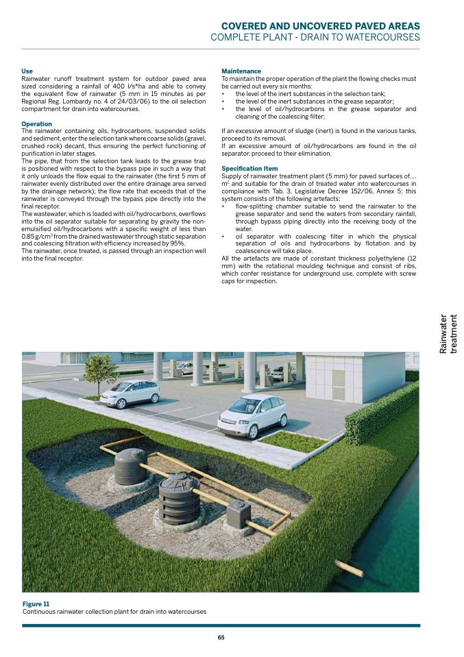
Figure 11
Continuous rainwater collection plant for drain into watercourses
65
R
a
i
n
w
a
t
e
r
t
r
e
a
t
m
e
n
t

