18
VALVOLE A SFERA MOTORIZZATE
MOTORIZED BALL VALVES
ESEMPI DI INSTALLAZIONE
INSTALLATION EXAMPLES
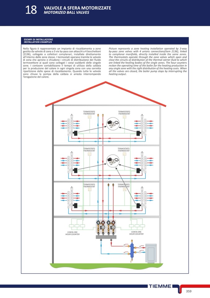
Nella figura
è rappresentato un impianto di riscaldamento a zone
gestito da valvole di zona a 3 vie by-pass con attacchi a 4 bocchettoni
(2136), collegate a collettori complanari, installate direttamente
all’interno delle zone stesse. I termostati operano tramite le valvole
di zona che aprono e chiudono i circuiti di distribuzione del fluido
termovettore ai quali sono collegati i corpi scaldanti delle singole
zone. I contaore contabilizzano il tempo di utilizzo della caldaia
per la produzione del calore in ogni singola zona con una corretta
ripartizione delle spese di riscaldamento. Quando tutte le valvole
sono chiuse la pompa della caldaia si arresta interrompendo
l’erogazione del calore.
Picture represents a zone heating installation operated by 3-way
by-pass zone valves with 4 unions connections(item 2136), linked
to complanar manifolds, directly installed inside the same zones.
The thermostats operate through the zone valves which open and
close the circuits of distribution of the thermal carrier fluid to which
are linked the heating bodies of the single zones. The hour counters
reckon the operating time of the boiler for the heating production in
any single zone with the right distribution of the heating costs. When
all the valves are closed, the boiler pump stops by interrupting the
heating output.
TERMOSTATO
TERMOSTATO
THERMOSTAT
THERMOSTAT
T
M
M
T
TERMOSTATO
THERMOSTAT
M
T
T
M
M
T
T
M
THERMOSTAT
TERMOSTATO
THERMOSTAT
TERMOSTATO
TERMOSTATO
THERMOSTAT
CONTA ORE
CONTA ORE
HOUR COUNTER
HOUR COUNTER
359

