1
8
VALVOLE A SFERA MOTORIZZAT
E
MOTORIZED BALL VALVE
S
ESEMPI DI INSTALLAZION
E
INSTALLATION EXAMPLES
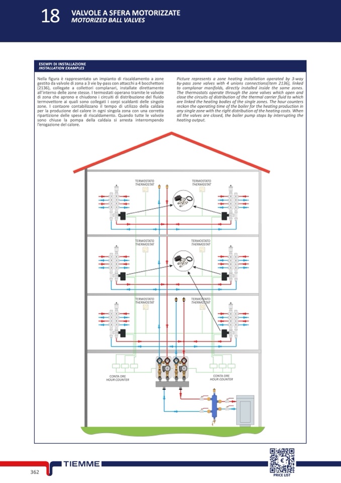
Nella figura è rappresentato un impianto di riscaldamento a zon
e
gestito da valvole di zona a 3 vie by-pass con attacchi a 4 bocchetton
i
(2136), collegate a collettori complanari, installate direttament
e
all’interno delle zone stesse. I termostati operano tramite le valvol
e
di zona che aprono e chiudono i circuiti di distribuzione del fluido
termovettore ai quali sono collegati i corpi scaldanti delle singol
e
zone. I contaore contabilizzano il tempo di utilizzo della caldaia
per la produzione del calore in ogni singola zona con una corrett
a
ripartizione delle spese di riscaldamento. Quando tutte le valvol
e
sono chiuse la pompa della caldaia si arresta interrompend
o
l’erogazione del calore
.
Picture represents a zone heating installation operated by 3-way
by-pass zone valves with 4 unions connections(item 2136), linke
d
to complanar manifolds, directly installed inside the same zones
.
The thermostats operate through the zone valves which open and
close the circuits of distribution of the thermal carrier fluid to whic
h
are linked the heating bodies of the single zones. The hour counter
s
reckon the operating time of the boiler for the heating production i
n
any single zone with the right distribution of the heating costs. Whe
n
all the valves are closed, the boiler pump stops by interrupting th
e
heating output
.
TERMOSTATO
THERMOSTA
T
TERMOSTAT
O
THERMOSTA
T
T
M
T
M
TERMOSTATO
THERMOSTA
T
TERMOSTATO
THERMOSTAT
T
M
T
M
TERMOSTATO
THERMOSTA
T
TERMOSTATO
THERMOSTAT
T
M
T
M
CONTA ORE
HOUR COUNTE
R
CONTA ORE
HOUR COUNTE
R
36
2
PRICE LIST

