TacoTherm Dual ZEPTO
Safety
2.3.1.2 Safety DCW valve (Option)
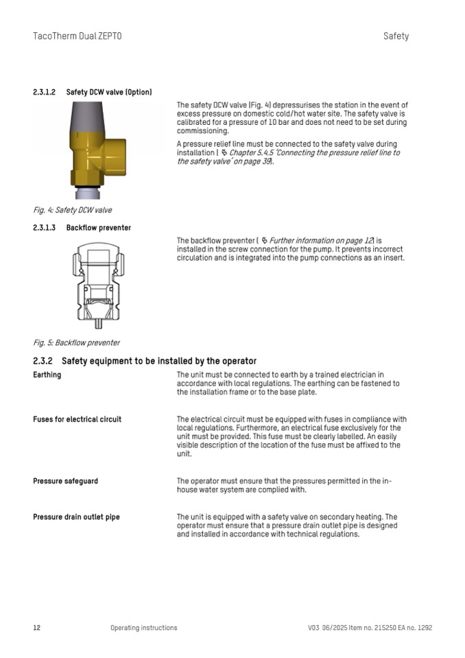
Fig. 4: Safety DCW valve
2.3.1.3 Backflow preventer
Fig. 5: Backflow preventer
The safety DCW valve (Fig. 4) depressurises the station in the event of
excess pressure on domestic cold/hot water site. The safety valve is
calibrated for a pressure of 10 bar and does not need to be set during
commissioning.
A pressure relief line must be connected to the safety valve during
installation (
Ä Chapter 5.4.5 ‘Connecting the pressure relief line to
the safety valve’ on page 39).
The backflow preventer (
Ä Further information on page 12) is
installed in the screw connection for the pump. It prevents incorrect
circulation and is integrated into the pump connections as an insert.
2.3.2 Safety equipment to be installed by the operator
Earthing
Fuses for electrical circuit
Pressure safeguard
Pressure drain outlet pipe
The unit must be connected to earth by a trained electrician in
accordance with local regulations. The earthing can be fastened to
the installation frame or to the base plate.
The electrical circuit must be equipped with fuses in compliance with
local regulations. Furthermore, an electrical fuse exclusively for the
unit must be provided. This fuse must be clearly labelled. An easily
visible description of the location of the fuse must be affixed to the
unit.
The operator must ensure that the pressures permitted in the in-
house water system are complied with.
The unit is equipped with a safety valve on secondary heating. The
operator must ensure that a pressure drain outlet pipe is designed
and installed in accordance with technical regulations.
12
Operating instructions
V03 06/2025 Item no. 215250 EA no. 1292

