Functional description
TacoTherm Dual ZEPTO
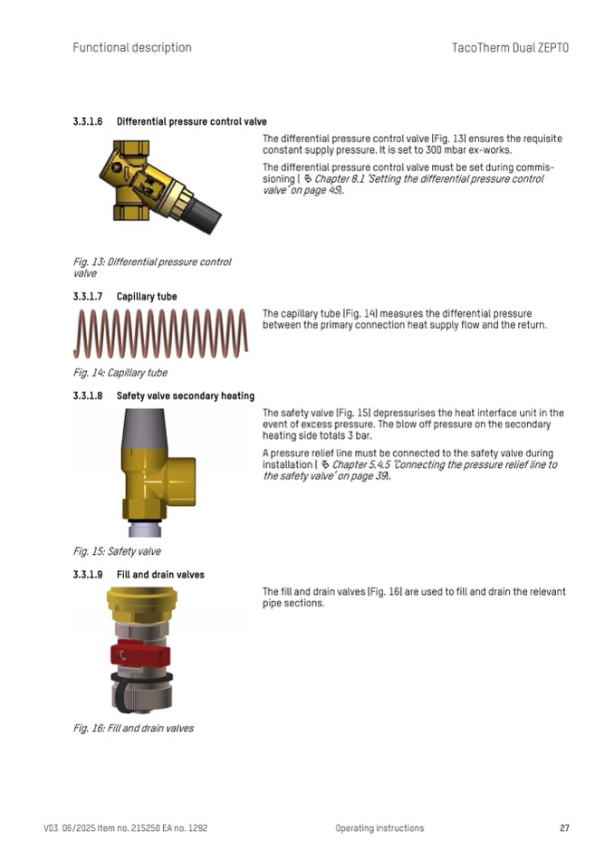
3.3.1.6 Differential pressure control valve
Fig. 13: Differential pressure control
valve
3.3.1.7 Capillary tube
Fig. 14: Capillary tube
3.3.1.8 Safety valve secondary heating
Fig. 15: Safety valve
3.3.1.9 Fill and drain valves
Fig. 16: Fill and drain valves
The differential pressure control valve (Fig. 13) ensures the requisite
constant supply pressure. It is set to 300 mbar ex-works.
The differential pressure control valve must be set during commis-
sioning ( Ä Chapter 8.1 ‘Setting the differential pressure control
valve’ on page 45).
The capillary tube (Fig. 14) measures the differential pressure
between the primary connection heat supply flow and the return.
The safety valve (Fig. 15) depressurises the heat interface unit in the
event of excess pressure. The blow off pressure on the secondary
heating side totals 3 bar.
A pressure relief line must be connected to the safety valve during
installation (
Ä Chapter 5.4.5 ‘Connecting the pressure relief line to
the safety valve’ on page 39).
The fill and drain valves (Fig. 16) are used to fill and drain the relevant
pipe sections.
V03 06/2025 Item no. 215250 EA no. 1292
Operating instructions
27

