Faults
TacoTherm Dual ZEPTO
6.
Install a new flow rate sensor (Fig. 44).
7.
Ensure that O-ring seals are available.
8.
Tighten the new flow rate sensor using an adjustable spanner.
9.
Tighten the primary hot water return line using an adjustable
spanner.
10. Restart the heat interface unit (
Ä Chapter 7 ‘Preliminary com-
missioning’ on page 42 and
Ä Chapter 8 ‘Final commissioning’
on page 45).
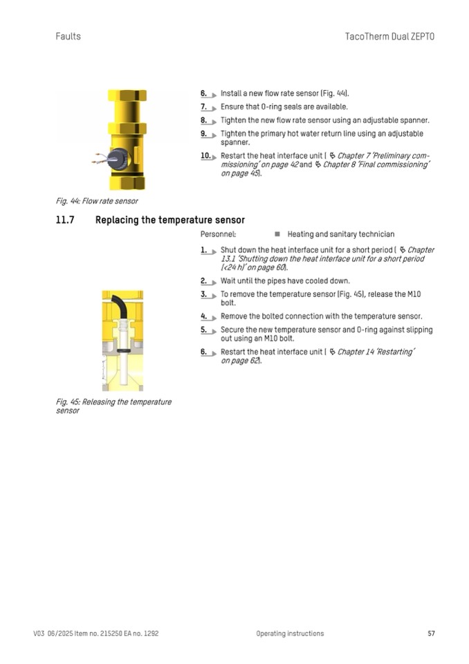
Fig. 44: Flow rate sensor
11.7
Replacing the temperature sensor
Personnel:
n Heating and sanitary technician
1.
Shut down the heat interface unit for a short period ( Ä Chapter
13.1 ‘Shutting down the heat interface unit for a short period
(<24 h)’ on page 60).
2.
Wait until the pipes have cooled down.
3.
To remove the temperature sensor (Fig. 45), release the M10
bolt.
4.
Remove the bolted connection with the temperature sensor.
5.
Secure the new temperature sensor and O-ring against slipping
out using an M10 bolt.
6.
Restart the heat interface unit ( Ä Chapter 14 ‘Restarting’
on page 62).
Fig. 45: Releasing the temperature
sensor
V03 06/2025 Item no. 215250 EA no. 1292
Operating instructions
57

