SISTEMI VRF ALL DC INVERTER GMV6 - GMV5 MINI E SLIM - GMV5 HOME
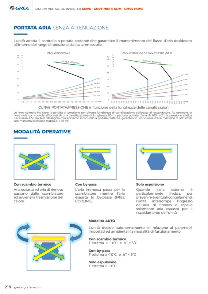
PORTATA ARIA SENZA ATTENUAZIONE
Figure 5-16 The flow/pressure diagram for GMV-VDR5PH/SA-S
GMV-VDR5PH/SA-S
GMV-VDR8PH/SA-S / GMV-VDR10PH/SA-S
L’unità adotta il controllo a portata costante che garantisce il mantenimento del flusso d’aria desiderato
g it if the resistance difference of pipeline at both sides of air outlet of fresh air unit is big.
all’interno del range di pressione statica ammissibile.
Figure 5-16 The flow/pressure diagram for GMV-VDR5PH/SA-S
c
t type on the curve is equal to that of straight pipe when friction coefficient is 0.02.
h
od
solamente aria esausta per il
to the detected temperature and humidity.
riscaldamento dell’unità
h
ods for unit, which are operating control mode and linkage control mode.
ERV+DX coil
curva di efficienza
curva di efficienza
Figure 5-17 The flow/pressure diagram for GMV-VDR8PH/SA-S/GMV-VDR10PH/SA-S
CURVE PORTATA/PRESSIONE in funzione della lunghezza delle canalizzazioni
Le linee colorate indicano la perdita di pressione per diverse lunghezze di canalizzazione collegate al recuperatore. Ad esempio, la
linea viola corrisponde all’ipotesi di una canalizzazione di lunghezza 80 m: per una portata d’aria di 400 m
3
/h, la pressione statica
NOTES!
necessaria è 55 Pa. Nel rettangolo rosa abbiamo il controllo a portata costante, garantendo un volume d’aria massimo di 500 m
3
/h
con massima pressione statica di 150 Pa.
MODALITÀ OPERATIVE
!"#$%& '
!"#$%& '
!"#$%& '
6.2 Operating mode
Figure 5-17 The flow/pressure diagram for GMV-VDR8PH/SA-S/GMV-VDR10PH/SA-S
Con scambio termico
(1)Heat exchange mode: when the unit detects that the indoor and outdoor ambient temperature difference i
Ariaesaustaedariadirinnovo
outdoor humidity is lower, the unit will activate heat exchange mode. Under such mode, fresh air and exh
passano dallo scambiatore
normal heat exchange.
(1)The length of duct type on the curve is equal to that of straight pipe when friction coefficient is 0.02.
(2)Before connecting air ducts, please finish the installation of the drainage system and test whether the dra
6 Product control
6.1 Control method
set two control methods for unit, which are operating control mode and linkage control mode.
When conducting operating control mode, the unit will operate according to the command input by the wired
When conducting linkage control mode, the unit should be connected into the control network of multi VRF u
will conduct linkage operation according to the operating status of multi VRF unit.
According to the actual using working conditions, and protect the internal components at the same time, this
operating modes for satisfying the using demands under different environmental conditions.
Con by-pass
Solo espulsione
L’aria immessa passa per la
Quando
l’aria
esterna
è
scambiatore mentre l’aria
particolarmente fredda, per
ed avviene la trasmissione del(2)By-pasesamuosdtea: whloen tbhey-upnaitsdseatect(sFRthEatEthe indoopr arnedveonutidreooervaemnbtieunatltiecmopnegraetularemdeiffnetrei,nce is small
n
g air ductsc,aplloearese. finish the installation of the drainageCsOysOteLmINaGnd).test whether the drainage is norlm’uanl.ità
interrompe l’ingresso
humidity is lower, the unit will activate by-pass mode. Under such mode, the unit will not conduct heat exc
r
ol
(3)Auto mode: the unit will determine to operate heat exchange mode, by-pass mode or other modes (defau
(4)Cooling mode: cooling mode of general air conditioner.
p
erating control mode, the unit will operate according to the command input by the wired controller.
Modalità AUTO
(5)Dry mode: dry mode of general air conditioner.
dell’aria di rinnovo e espelle
L’unità decide autonomamente, in relazione ai parametri
(6)Heating mode: heating mode of general air conditioner.
n
kage control mode, the unit should be connected into the control network of multi VRF unit, then the unit
p
eration according to the operating status of multi VRF unit.
o
de
t
ual using working conditions, and protect the internal components at the same time, this unit has multiple
a
tisfying the using demands un!d"e#r$d%if&fe'rent environmental conditions.
T esterna ≥ -10°C e ∆T < 3°C
m
ode: when the unit detects that the indoor and outdoor ambient temperature difference is large and the
y
is lower, the unit will activate heat exchange mode. Under such mSodloe, efrsepshualsiriaondeexhaust air conduct
h
ange.
w
hen the unit detects that the indoor and outdoor ambient temperature difference is small and the outdoor
r
, the unit will activate by-pass mode. Under such mode, the unit will not conduct heat exchange.
u
nit will determine to operate heat exchange mode, by-pass mode or other modes (default mode) according
218 gree.argoclima.com
e
mperature and humidity.
o
o
l
i
n
g
m
o
d
e
o
f
g
e
n
e
r
a
l
a
i
r
c
o
n
d
i
t
i
o
n
e
r
.
impostati ed ambientali la modalità di funzionamento.
Con scambio termico
27
T esterna ≥ -10°C e ∆T ≥ 3°C
Con by-pass
T esterna < -10°C

