92
Manifolds and Temperature Control Units - Product Guide
Tel. +39 0425 75 88 11
Additional bypass section
Code
Mod.
User connections
Pump connections
11 73 42
DN25
1" F
1"-1/2F
unit
Specifications
Kit consisting of by-pass + two 3-way valves equipped with handle with thermom-
eter-holder with red ring 0°C-120 °C (flow) and blue ring 0°C-120° C (return), re-
spectively. In brass CW617N (CW614N). Yellow brass finish Caps and gaskets not
included
Use
The by-pass section is used by systems that can work with significant flow
variations, i.e. those that largely use thermostatic valves or motorised valves, so
as to ensure recirculation with a flow proportional to the amount of valves which
close, limiting the maximum value of the differential pressure generated by the
circulator.
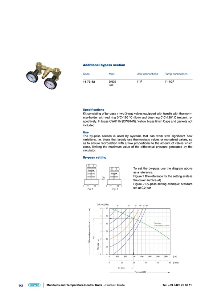
By-pass setting
To set the by-pass use the diagram above
as a reference.
Figure 1 The reference for the setting scale is
the cover surface /A)
Figure 2 By-pass setting example: pressure
set at 0,2 bar
Flow rate [l/h]
Circulator
characteristic curve
D
i
f
f
e
r
e
n
t
i
a
l
p
r
e
s
s
u
r
e
[
m
.
c
.
a
.
]
O
p
e
n
i
n
g

