DIC
Ventilatori centrifughi pale avanti
Forward curved blade centrifugal fans
Versioni /Versions:
La serie non rientra nel campo di applicazione
della Direttiva ErP 2009/125/UE.
The series is not affected
by ErP Directive 2009/125/UE.
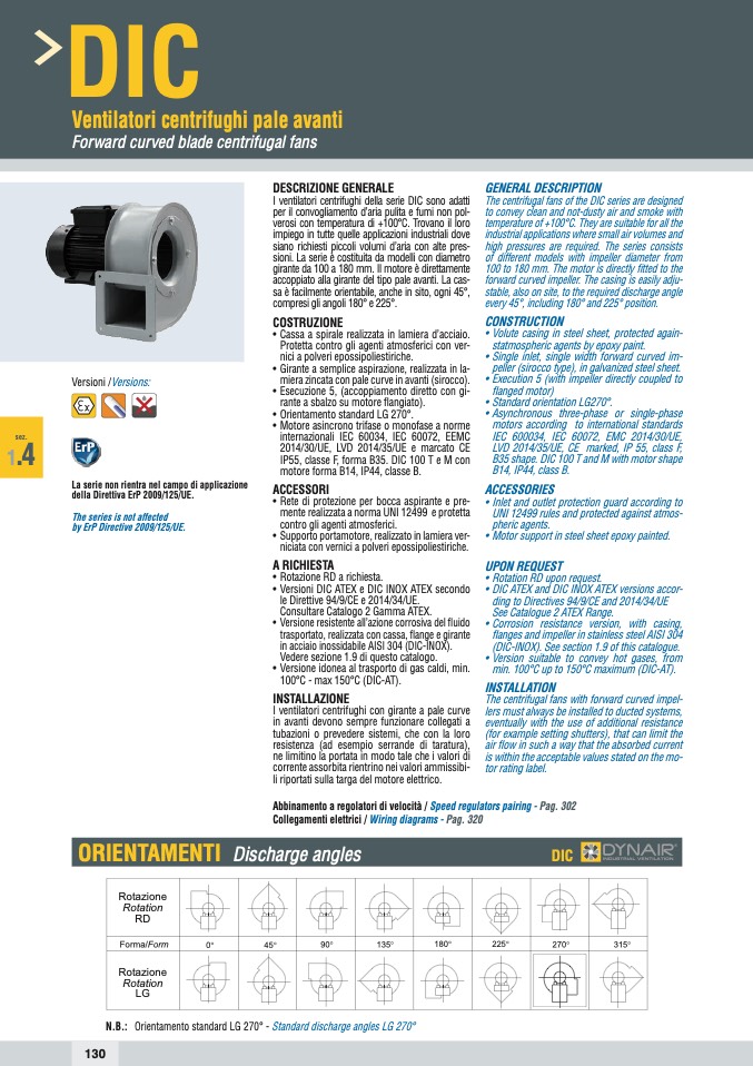
DESCRIZIONE GENERALE
I ventilatori centrifughi della serie DIC sono adatti
per il convogliamento d’aria pulita e fumi non pol-
verosi con temperatura di +100°C. Trovano il loro
impiego in tutte quelle applicazioni industriali dove
siano richiesti piccoli volumi d’aria con alte pres-
sioni. La serie è costituita da modelli con diametro
girante da 100 a 180 mm. Il motore è direttamente
accoppiato alla girante del tipo pale avanti. La cas-
sa è facilmente orientabile, anche in sito, ogni 45°,
compresi gli angoli 180° e 225°.
COSTRUZIONE
• Cassa a spirale realizzata in lamiera d’acciaio.
Protetta contro gli agenti atmosferici con ver-
nici a polveri epossipoliestiriche.
• Girante a semplice aspirazione, realizzata in la-
miera zincata con pale curve in avanti (sirocco).
• Esecuzione 5, (accoppiamento diretto con gi-
rante a sbalzo su motore flangiato).
• Orientamento standard LG 270°.
• Motore asincrono trifase o monofase a norme
internazionali IEC 60034, IEC 60072, EEMC
2014/30/UE, LVD 2014/35/UE e marcato CE
IP55, classe F, forma B35. DIC 100 T e M con
motore forma B14, IP44, classe B.
ACCESSORI
• Rete di protezione per bocca aspirante e pre-
mente realizzata a norma UNI 12499 e protetta
contro gli agenti atmosferici.
• Supporto portamotore, realizzato in lamiera ver-
niciata con vernici a polveri epossipoliestiriche.
A RICHIESTA
• Rotazione RD a richiesta.
• Versioni DIC ATEX e DIC INOX ATEX secondo
le Direttive 94/9/CE e 2014/34/UE.
Consultare Catalogo 2 Gamma ATEX.
• Versione resistente all’azione corrosiva del fluido
trasportato, realizzata con cassa, flange e girante
in acciaio inossidabile AISI 304 (DIC-INOX).
Vedere sezione 1.9 di questo catalogo.
• Versione idonea al trasporto di gas caldi, min.
100°C - max 150°C (DIC-AT).
INSTALLAZIONE
I ventilatori centrifughi con girante a pale curve
in avanti devono sempre funzionare collegati a
tubazioni o prevedere sistemi, che con la loro
resistenza (ad esempio serrande di taratura),
ne limitino la portata in modo tale che i valori di
corrente assorbita rientrino nei valori ammissibi-
li riportati sulla targa del motore elettrico.
GENERAL DESCRIPTION
The centrifugal fans of the DIC series are designed
to convey clean and not-dusty air and smoke with
temperature of +100°C. They are suitable for all the
industrial applications where small air volumes and
high pressures are required. The series consists
of different models with impeller diameter from
100 to 180 mm. The motor is directly fitted to the
forward curved impeller. The casing is easily adju-
stable, also on site, to the required discharge angle
every 45°, including 180° and 225° position.
CONSTRUCTION
• Volute casing in steel sheet, protected again-
statmospheric agents by epoxy paint.
• Single inlet, single width forward curved im-
peller (sirocco type), in galvanized steel sheet.
• Execution 5 (with impeller directly coupled to
flanged motor)
• Standard orientation LG270°.
• Asynchronous three-phase or single-phase
motors according to international standards
IEC 600034, IEC 60072, EMC 2014/30/UE,
LVD 2014/35/UE, CE marked, IP 55, class F,
B35 shape. DIC 100 T and M with motor shape
B14, IP44, class B.
ACCESSORIES
• Inlet and outlet protection guard according to
UNI 12499 rules and protected against atmos-
pheric agents.
• Motor support in steel sheet epoxy painted.
UPON REQUEST
• Rotation RD upon request.
• DIC ATEX and DIC INOX ATEX versions accor-
ding to Directives 94/9/CE and 2014/34/UE
See Catalogue 2 ATEX Range.
• Corrosion resistance version, with casing,
flanges and impeller in stainless steel AISI 304
(DIC-INOX). See section 1.9 of this catalogue.
• Version suitable to convey hot gases, from
min. 100°C up to 150°C maximum (DIC-AT).
INSTALLATION
The centrifugal fans with forward curved impel-
lers must always be installed to ducted systems,
eventually with the use of additional resistance
(for example setting shutters), that can limit the
air flow in such a way that the absorbed current
is within the acceptable values stated on the mo-
tor rating label.
sez.
1
.4
Abbinamento a regolatori di velocità / Speed regulators pairing - Pag. 302
Collegamenti elettrici / Wiring diagrams - Pag. 320
ORIENTAMENTI Discharge angles
DIC
Rotazione
Rotation
RD
Forma/Form
0°
45°
90°
135°
180°
225°
270°
315°
Rotazione
Rotation
LG
N.B.: Orientamento standard LG 270° - Standard discharge angles LG 270°
130

