DIMENSIONAL
I
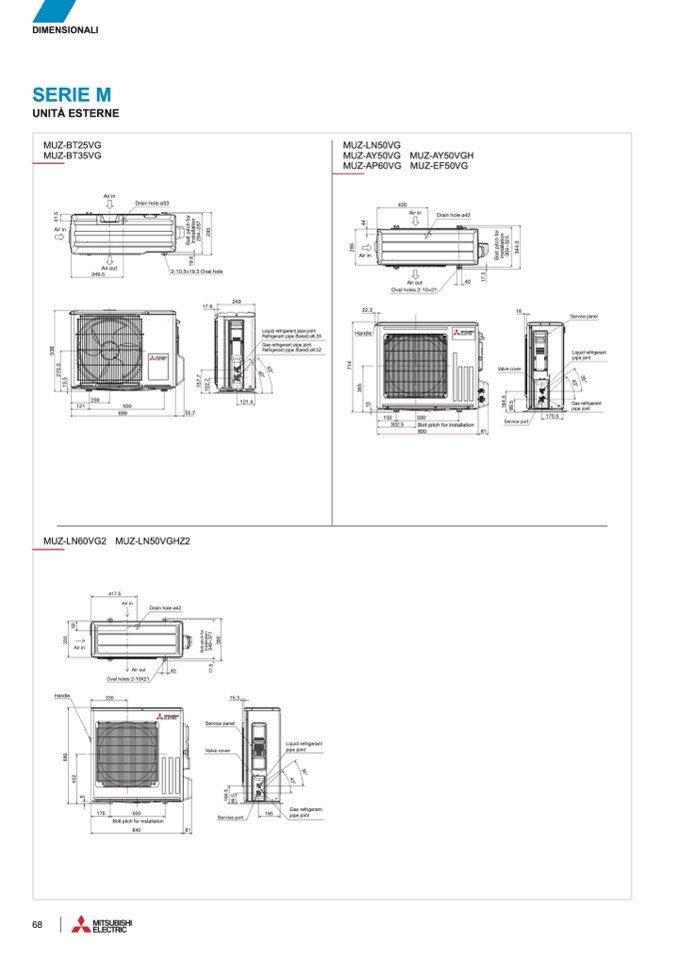
SERIE M
MUZ-WN25VA MUZ-WN35VA
UNITÀ ESTERN
E
MUZ-DM25VA MUZ-DM35V
A
MUZ-WN25VA MUZ-WN35VA
MUZ-WN25VA MUZ-WN35VA
MUZ-HJ25VA MUZ-HJ35VA
MUZ-HR25VF
MUZ-HR35VF
MUZ-HR25VF
MUZ-HR25VF
MUZ-DM25VA MUZ-DM35V
A
MUZ-DM25VA MUZ-DM35V
A
MUZ-DW25VF MUZ-DW35VF
MUZ-HR35VF
MUZ-HR35VF
MUZ-BT25VG
MUZ-HJ25VA MUZ-HJ35VA
MUZ-HJ25VA MUZ-HJ35VA
OUTDOOR UNI
T
MUZ-BT35VG
MUZ-DW25VF MUZ-DW35VF
MUZ-DW25VF MUZ-DW35VF
OUTDOOR UNI
T
OUTDOOR UNI
T
Air i
n
Drain hole ø3
3
4
1
.
5
Air i
n
Air i
n
Drain hole ø3
3
Drain hole ø3
3
Air in
4
1
.
5
4
1
.
5
Air in
Air in
B
o
l
t
p
i
t
c
h
f
o
r
i
n
s
t
a
l
l
a
t
i
o
n
B
o
l
t
p
i
t
c
h
f
o
r
B
o
l
t
p
i
t
c
h
f
o
r
1
9
.
6
i
n
s
t
a
l
l
a
t
i
o
n
i
n
s
t
a
l
l
a
t
i
o
n
2
9
4
~
2
6
7
2
9
4
~
2
6
7
2
9
4
~
2
6
7
2
8
5
2
8
5
2
8
5
2-10.3×19.3 Oval hol
e
1
9
.
6
1
9
.
6
2-10.3×19.3 Oval hol
e
2-10.3×19.3 Oval hol
e
17.9
17.9
17.9
1
0
2
.
7
1
0
2
.
7
1
0
2
.
7
Air out
349.
5
Air out
Air out
349.
5
349.
5
24
9
24
9
24
9
2
7
0
.
3
2
7
0
.
3
1
3
.
5
1
3
.
5
5
3
8
5
3
8
2
7
0
.
3
1
3
.
5
5
3
8
259
55.7
1
5
7
.
7
1
5
7
.
7
1
5
7
.
7
121.
4
259
259
12
1
50
0
699
12
1
12
1
50
0
50
0
699
699
MUZ-RW50VGH
Z
MUZ-LN60VG
2
MUZ-LN50VGHZ
2
MUZ-RW50VGH
Z
MUZ-RW50VGH
Z
MUZ-LN60VG
2
MUZ-LN60VG
2
OUTDOOR UNIT
MUZ-LN50VGHZ
2
MUZ-LN50VGHZ
2
MUZ-LN60VG2 MUZ-LN50VGHZ
2
OUTDOOR UNIT
OUTDOOR UNIT
417.5
Drain hole ø42
121.
4
121.
4
55.7
55.7
Air in
417.5
417.5
5
0
Air in
Air in
Drain hole ø42
Drain hole ø42
3
3
0
5
0
5
0
Air in
Handle
3
3
0
3
3
0
Air in
Air in
8
8
0
8
8
0
8
8
0
Handle
Handle
Air ou
t
40
B
o
l
t
p
i
t
c
h
f
o
r
i
n
s
t
a
l
l
a
t
i
o
n
B
o
l
t
p
i
t
c
h
f
o
r
B
o
l
t
p
i
t
c
h
f
o
r
i
n
s
t
a
l
l
a
t
i
o
n
i
n
s
t
a
l
l
a
t
i
o
n
3
4
9
~
3
7
1
3
9
0
3
4
9
~
3
7
1
3
4
9
~
3
7
1
1
7
.
5
3
9
0
3
9
0
Oval holes 2-10X21
Air ou
t
Air ou
t
40
40
1
7
.
5
1
7
.
5
330
15.
3
Oval holes 2-10X21
Oval holes 2-10X21
15.
3
15.
3
Service panel
Service panel
Service panel
Valve cover
330
330
Valve cover
Valve cover
4
5
2
4
5
2
4
5
2
8
1
6
4
.
5
9
9
.
5
175
500
8 8
Bolt pitch for installatio
n
840
8
1
Service port
Service port
1
6
4
.
5
1
6
4
.
5
9
9
.
5
9
9
.
5
Service port
175
500
175
500
Bolt pitch for installatio
n
Bolt pitch for installatio
n
840
8
1
840
8
1
6
8
MUZ-BT25V
G
MUZ-BT35V
G
MUZ-BT25V
G
MUZ-BT25V
G
MUZ-BT35V
G
MUZ-BT35V
G
Liquid refrigerant pipe joint
Refrigerant pipe (
flared) ø6.35
Gas refrigerant pipe join
t
Refrigerant pipe (
flared) ø9.52
Liquid refrigerant pipe joint
Liquid refrigerant pipe joint
Refrigerant pipe (
flared) ø6.35
Refrigerant pipe (
flared) ø6.35
Gas refrigerant pipe join
t
Gas refrigerant pipe join
t
4
3
°
4
0
°
Refrigerant pipe (
flared) ø9.52
Refrigerant pipe (
flared) ø9.52
4
3
°
4
3
°
4
0
°
4
0
°
MUZ-RW25VGHZ MUZ-RW35VGH
Z
MUZ-LN50V
G
MUZ-RW25VGHZ MUZ-RW35VGH
Z
MUZ-RW25VGHZ MUZ-RW35VGH
Z
MUZ-FT35/50VGHZ
MUZ-LN50V
G
MUZ-LN50V
G
MUZ-AY50VG MUZ-AY50VGH MUZ-AP60V
G
MUZ-FT35/50VGHZ
MUZ-FT35/50VGHZ
MUZ-EF50VG
MUZ-LN50V
G
MUZ-AY50VG MUZ-AY50VGH MUZ-AP60V
G
MUZ-AY50VG MUZ-AY50VGH MUZ-AP60V
G
MUZ-HR60VF MUZ-HR71VF
MUZ-AY50VG MUZ-AY50VGH
MUZ-AP60VG MUZ-EF50VG
MUZ-EF50VG
MUZ-EF50VG
OUTDOOR UNIT
MUZ-HR60VF MUZ-HR71VF
MUZ-HR60VF MUZ-HR71VF
400
OUTDOOR UNIT
OUTDOOR UNIT
Air in
Drain hole ø42
4
4
400
400
Air in
Air in
Drain hole ø42
Drain hole ø42
2
8
5
4
4
4
4
Air
in
2
8
5
2
8
5
Air i
n
Air in
1
7
.
5
B
o
l
t
p
i
t
c
h
f
o
r
i
n
s
t
a
l
l
a
t
i
o
n
B
o
l
t
p
i
t
c
h
f
o
r
B
o
l
t
p
i
t
c
h
f
o
r
i
n
s
t
a
l
l
a
t
i
o
n
i
n
s
t
a
l
l
a
t
i
o
n
3
0
4
~
3
2
5
3
0
4
~
3
2
5
3
0
4
~
3
2
5
3
4
4
.
5
3
4
4
.
5
3
4
4
.
5
Air out
40
Oval holes 2-10×2
1
1
7
.
5
1
7
.
5
Air out
Air out
40
40
22.3
16
Oval holes 2-10×2
1
Oval holes 2-10×2
1
Handle
22.3
16
22.3
16
7
1
4
7
1
4
7
1
4
3
6
5
3
6
5
3
6
5
Handle
Handle
Valve cover
Valve cover
Valve cover
1
6
4
.
5
9
9
.
5
1
0
1
0
1
0
150
500
170.
5
302.5
150
150
302.5
302.5
Bolt pitch for installatio
n
800
81
500
500
81
81
1
6
4
.
5
1
6
4
.
5
9
9
.
5
9
9
.
5
Service port
170.5
170.
5
Service port
Service port
Bolt pitch for installatio
n
Bolt pitch for installatio
n
800
800
Liquid refrigeran
t
pipe join
t
Liquid refrigeran
t
Liquid refrigeran
t
pipe join
t
pipe join
t
3
5
°
4
3
°
19
5
3
5
°
3
5
°
4
3
°
4
3
°
Gas refrigerant
pipe join
t
19
5
19
5
Gas refrigerant
Gas refrigerant
pipe join
t
pipe join
t
Unit : mm
Unit : mm
Unit : mm
Service panel
Service panel
Service panel
Liquid refrigerant
pipe join
t
Liquid refrigerant
Liquid refrigerant
pipe join
t
pipe join
t
4
3
°
3
5
°
4
3
°
4
3
°
3
5
°
3
5
°
Gas refrigerant
pipe joint
Gas refrigerant
Gas refrigerant
pipe joint
pipe joint

