GENERATORI PER LA PRODUZIONE DI VAPORE | STEAM BOILERS
VAPOPREXLVP
160÷1250
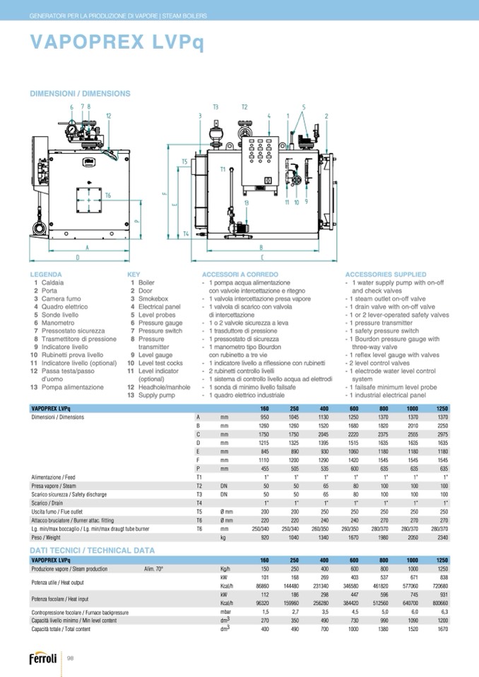
VAPOPREX LVPq
DIMENSIONI / DIMENSIONS
Legenda
Key
LEGENDA
KEY
ACCESSORI A CORREDO
-
-
-
-
-
40
-
0
40
-
0
269
ACCESSORIES SUPPLIED
- 1 water supply pump with on-off
and check valves
- 1 steam outlet on-off valve
1 Caldaia
8 Trasmettitore di Pressione
1 Boiler
1 Caldaia
2 Porta
1 Boiler
9 Indicatore Livello
1 pompa acqua alimentazione
2 Porta
3 Camera Fumo
2 Door
10 Rubinetti Prova Livello
2 Door
9 Level Gauge
3 Camera fumo
4 Quadro Elettrico
3 Smokebox
11 Indicatore Livello (optional)
3 Smokebox
10 Level test Cocks
4 Quadro elettrico
5 Sonde Livello
6 M
5anoSmoentdroe livello
7 Pr6essMoasntaotomSeitcruorezza
4 Electrical panel
12 Passa Testa / Passo D'uomo
4 Electrical panel
11 Level Indicator (optional)
7 Pressostato sicurezza
VAPOPREX
8
LVP
T
q
rasmettitore di pressione
Produzione V
9
apor
I
e
n
-
d
S
i
t
c
eam
to
Pro
e
du
l
c
i
t
v
io
e
n A
ll
l
o
im. 70°C Kg/h
7 Pressure switch
1
8
60
Pressure
250
150
transmitte
25
r
0
1
9
01
Level gau
1
g
68
e
1
86
0
860
Level tes
14
t
4
c
48
o
0
cks
1
112
Level indi
1
c
8
a
6
tor
96320
(optional
1
)
59960
1000
1000
671
1250
1250
838
10 Rubinetti prova livello
KW
Potenza utile - Heat output
Dimensioni / D
a
i
li
m
ent
s
a
i
z
o
io
n
n
s
e - feed T1
presa vapore - steam T2
scarico sicurezza - safety discharge T3
scarico - drain T4
uscita fumo - flue outlet T5
attacco bruciatore - burner attac. fitting
T6
lg. min/max boccaglio - lg. min/max draugt tube burner
mm
mm
mm
mm
mm
mm
mm
DN
DN
1"
DN 80
DN 80
1"
250
240
260/350
1250
1680
2220
1515
1060
950
1"
126
D
0
N 100
1045
1"
1260
DN 100
270
280/370
1130
1"
1250
1520
DN 100
1680
800
1000
1250
1370
1370
1370
1820
2010
2250
2375
2555
2975
1635
1635
1635
1180
1180
1180
1545
1545
1545
635
635
635
1”
1”
1”
100
100
100
100
100
100
1”
1”
1”
250
250
250
270
270
270
280/370
280/370
280/370
1980
2050
2340
6
78
T
3
T
2
5
12
3
4
1
2
11 Indicatore livello (optio
Kc
n
a
a
l/h
l)
12 Passa testa/passo
KW
231
-
340
1 indicat
3
o
46
re
580
livello a r
4
i
6
fl
1
e
82
s
0
sione con
577
r
0
u
6
b
0
inetti
29
-
8
2 rubinett
4
i
4
c
7
ontrollo live
59
ll
6
i
745
720680
- 2 level control valves
931
- 1 electrode water level control
Potenza focolare - Heat input
d’uomo
Kcal/h
256
-
280
1 sistem
3
a
84
d
42
i
0
controllo
51
l
2
iv
56
e
0
llo acqua
64
a
07
d
00
elettrodi
800660
system
13 Pompa alimentazione
12
Headhole/manhole
-
1 sonda di minimo livello failsafe
- 1 failsafe minimum level probe
- 1 industrial electrical panel
Contropressionefocolare- Furnacebackpressure
mbar
1,5
2,7
3,5
4,5
5,0
6,3
1200
1520
1670
Capacitàlivellominimo - Min.levelcapacity
Capacitàtotale
- Totalcapacity
Peso-Weig
V
h
A
t
POPREXLVPq
bar
13
Supply pump
-
1 quadro elettrico industriale
6,0
1090
T6
T5
T1
T4
13
11 10 9
8 Pressure Transmitter
A
B
D
C
13 Pompa Alime
5ntaLzeiovneel probes
6 Pressure gauge
5 Level Probes
12 Headhole / Manhole
di inte6rcPertetaszsiuorneegauce
13 Supply Pump
1 o 2 7vaPlvreoslesusriecuSrewzitzcah a leva
1 trasduttore di pressione
1 pressos
6
t
0
a
0
to di sicure
80
z
0
za
1 manom
6
e
00
tro tipo Bou
8
r
0
d
0
on
con rubin
4
e
0
t
3
to a tre vie
537
Ø mm
Ø mm
200
200
250
250
250
250
Scarico / Drain
T4
1”
1”
1”
1”
400
1"
1"
A
1"
DN 50
DN 50
B
DN 65
E
845
890
930
1180
1180
1180
Uscita fumo / Flue outlet
T5
Ø mm
250
250
technical specif
1ic0at4io0ns and accessorie1s 3m4ay0be subject to va1ra6ti7on0.
F
1110
1200
1290
1420
600
200
200
1545
P
455
505
535
635
635
635
Attacco bruciatore / Burner attac. fitting
T6
Lg. min/max boccaglio / Lg. min/max draugt tube burner
T6
Ø mm
mm
st
kregsses that appearance and/or9si2ze0,
160
Kg/h
150
kW
101
Kcal/h
86860
kW
112
Kcal/h
96320
mbar
1,5
dm3
270
dm3
400
240
240
490
700
1000
1380
C
1"
1"
D
1"
1750
1215
1"
1750
890
2045
2220
1395
1"
1515
1290
1420
535
600
DN 50
DN 50
DN 65
DN 100
DN 100
1325
1"
DN 100
220
220
240
F
250/340
250/340
260/350
P
270
270
A
950
1045
1130
1370
Alimentazione / Feed
T1
1”
1”
1”
1”
B
1260
1260
1520
Presa vapore / Steam
C
1750
1750
T
2
2
045
D
I
M
E
N
S
I
O
N
S
I
c
-
a
D
r
I
i
M
c o
E
N
s
S
i c
I
O
u r
N
e
S
z z a / S a f e t y d i s c h a
D
r g e
1
2
1
5
1325
T
1
3
95
1820
2010
5
2
0
375
50
2555
5
1
0
635
50
1635
2250
65
2975
80
FERROLI S.p.A. si riserva a termini di legge la propietà del presente disegno con divieto di riprodurlo o comunicarlo senza sua autorizzazione. L'Azienda precisa che le caratteristiche estetiche e/o dimensionali, i dati tecnici e gli accessori possono essere soggetti a variazione.
FERROLI S.p.A.
re
Pseervsedoac/coWrdiengilgy hcutrrent laws this drawing's property with its reproducing and development prohibition without his authorization.
DATI TECNICI / TECHNICAL DATA
The Company
VAPOPREX LVPq
Produzione vapore / Steam production
Potenza utile / Heat output
Potenza focolare / Heat input
Contropressione focolare / Furnace backpressure
Capacità livello minimo / Min level content
Capacità totale / Total content
Alim. 70°
250
400
250
400
168
269
144480
231340
186
298
159960
256280
2,7
3,5
350
490
490
700
600
800
1000
1250
600
800
1000
1250
403
537
671
838
346580
461820
577060
720680
447
596
745
931
384420
512560
640700
800660
4,5
5,0
6,0
6,3
730
990
1090
1200
1000
1380
1520
1670
98
E
845
930
1060
con valvole intercettazione e ritegno
1 valvola intercettazione presa vapore
1 valvola di scarico con valvola
- 1 drain valve with on-off valve
- 1 or 2 lever-operated safety valves
- 1 pressure transmitter
- 1 safety pressure switch
- 1 Bourdon pressure gauge with
three-way valve
- 1 reflex level gauge with valves
dm3
dm3
kg
920
1040
1340
1670
160
1980
250
2050
400
2340
600
270
350
490
730
990
1200
455
505
1110
A
T
T
A
C
C
H
I
-
F
I
T
T
I
N
G
P
F
E
280/370
1370
1370
280/370
1545
1545
220
220
250/340
250/340
260/350
260/350
65
1635
80

