POWER PLUS BOX / Moduli Termici Condensing da esterno
DISEGNI TECNICI
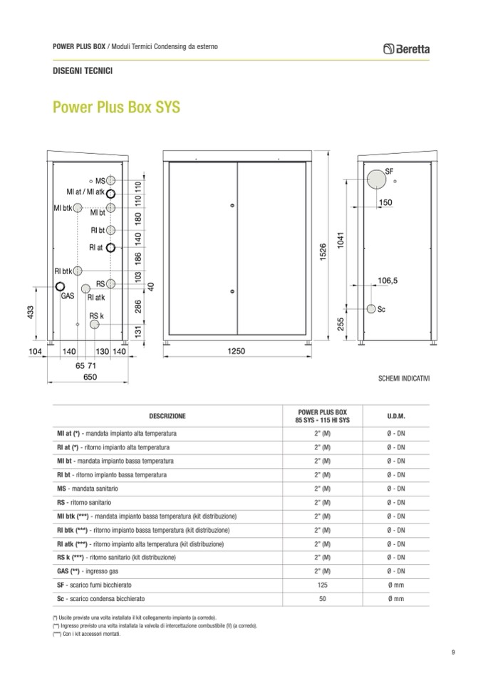
Power Plus Box SYS
1250
MS
MI at / MI atk
MI btk
RI btk
GAS
140
65 71
650
MI bt
RI bt
RI at
RS
RI atk
RSk
130
140
104
SF
150
106,5
Sc
SCHEMI INDICATIVI
U.D.M.
Ø - DN
Ø - DN
Ø - DN
Ø - DN
Ø - DN
Ø - DN
Ø - DN
Ø - DN
Ø - DN
Ø - DN
Ø - DN
Ø mm
Ø mm
POWER PLUS BOX
85 SYS - 115 HI SYS
2” (M)
2” (M)
2” (M)
2” (M)
2” (M)
2” (M)
2” (M)
2” (M)
2” (M)
2” (M)
2” (M)
125
50
DESCRIZIONE
MI at (*) - mandata impianto alta temperatura
RI at (*) - ritorno impianto alta temperatura
MI bt - mandata impianto bassa temperatura
RI bt - ritorno impianto bassa temperatura
MS - mandata sanitario
RS - ritorno sanitario
MI btk (***) - mandata impianto bassa temperatura (kit distribuzione)
RI btk (***) - ritorno impianto bassa temperatura (kit distribuzione)
RI atk (***) - ritorno impianto alta temperatura (kit distribuzione)
RS k (***) - ritorno sanitario (kit distribuzione)
GAS (**) - ingresso gas
SF - scarico fumi bicchierato
Sc - scarico condensa bicchierato
(*) Uscite previste una volta installato il kit collegamento impianto (a corredo).
(**) Ingresso previsto una volta installata la valvola di intercettazione combustibile (V) (a corredo).
(***) Con i kit accessori montati.
9
4
3
3
1
3
1
2
8
6
1
0
3
1
8
6
1
4
0
1
8
0
1
1
0
1
1
0
4
0
2
5
5
1
5
2
6
1
0
4
1

