4
4 - 1
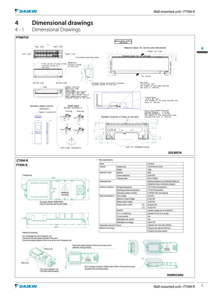
FTXM71R
Left side
Dimensional drawings
Dimensional Drawings
CTXM-R
FTXM-R
• Outside size
•
Main specifications
Items
Outside
Material of resin
Applicable laws
Ambient conditions
Basic specifications
• Method of mounting
Rear side
Rear side
Bottom side
Flap
Wireless remote control
(ARC466A67)
Bottom side
Gas pipe
·
U
15.9 mm· CuT
The length of the pipe outside
the unit is ·400·mm.
Liquid pipe
·
U
6.4 mm· CuT
The length of the pipe outside the
unit is ·460·mm.
Drain hose Connecting part
Inside diameter: ·
U
14·mm
Outside diameter: ·
U
16·mm
The length of the connection hose
outside the unit is ·440·mm.
Signal transmitter
58.5
23.5
Cooling
Heating
998
FTXM71R2V1B
Required space for service and ventilation
4
Indoor air flow
Located inside of
the unit
Located inside
292
Don’t blockage the vent of streamer unit.
Ensure the exit wind speed 0.2m/sec of the vent.
Ensure the spatial distance 8.5mm over at the vent of streamer unit.
R20
Flow of air
0.2m/s over
The vent of streamer unit
(The other side the same)
Ensure the spatial distance 8.5mm over at the vent of
streamer unit by products.
WARNING
VOLTAGE
R20
150.9
Outside size
Weight
Material
Flame retardance
Tracking index
Storage temperature
Operating ambient temperature
Operating ambient humidity
Input voltage
Maximum output voltage
Rating output voltage
Rating output current
ON/OFF
Hi ⇔ Lo Switching
Current monitor
Detectable over current
Detectable low voltage
Contents
150.9×46.9×27.5mm
100g
ABS
UL94-5VA
Over CTI600V
Electrical Appliance and Material Safety Act
IEC60335-1(4th), IEC60335-2-65(4th)
-25~70 (Non-Energization)
-10~60 (Energization)
5~95%RH (No dew deposit)
14V±5%
6.5±0.5kV
5.0±0.5kV
55.5μA±10%
10μA±10%
Inputted voltage into Vin (ON/OFF)
Inputted 5V into HL (Loe tap)
Yes
Yes
Under 3kV
4.26ml/hr (Hi 14±2°C 50±10%RH)
Fixing by the right and left hook
Fixing by the screw section
WARNING
VOLTAGE
3D095530G
Connector (Model: B04B-PASK)
(1pin:Vin 2pin:Ans 3pin:HL 4pin:GND)
138.4
Hi
Lo
10°
5°
20°
15°
55°
25°
65°
Dry
45°
Standard location of holes in the wall
Right side
Minimum space for air passage
Air outlet
Including mounting plate
Front grille fixing screws
Nameplate
45°
75°
20°
55°
998
746.6
WARNING
VOLTAGE
Fan
15°
65°
130
of the unit
289.1
184.7
Signal receiver
Operation lamp
Timer lamp
Intelligent Eye sensor
Intelligent Eye lamp
Indoor unit On/OFF switch
Room temperature sensor
Located inside of the unit
Blade angle
Up/down (automatic)
75°
Left/right (automatic)
Hole for embedded piping
10°
120.5
50 MIN
Terminal block with earth terminal
Located inside of the unit
50 MIN
53
170
170
65
Generation amount of Ozone
Method of mounting
Don’t arrange conduction material within 20mm of the aluminum tape
(Except for the unit fixing screw).
Applicable models
Wall mounted unit • FTXM-R
O
8
0
45v
45v
2D130576
WARNING
VOLTAGE
8
.
5
8
.
5
2
0
2
7
.
5
4
6
.
9
5
2
2
9
9
1
4
.
4
5
2
1
8
9
2
1
.
1
3
0
2
9
9
S
e
r
v
i
c
e
s
p
a
c
e
S
e
r
v
i
c
e
s
p
a
c
e
3
0
M
I
N
Wall mounted unit • FTXM-R
11

