GENERATORI PER LA PRODUZIONE DI VAPORE | STEAM BOILERS
VAPOPREX HVPq
12
T1
T6
10
9
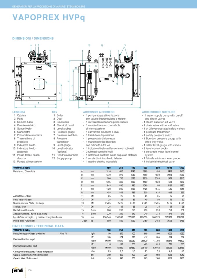
1 Caldaia
8 Trasmettitore di Pressione
1 Caldaia
2 Porta
1 Boiler
9 Indicatore Livello
2
3 C
Paomrteara Fumo
10 Indicatore Li
2
vell
D
o
o
(op
r
tional)
11 Passa Testa / Passo D'uomo
3 Camerafumo
3 Smokebox
12 Pompa Alimentazione
4 Quadro Elettrico
5 Sonse Livello
4 Electricalpanel
5 Levelprobes
4 Quadroelettrico
6 Manometro
5 Sondelivello
7 Pressostato Sicurezza
6 Pressuregauge
160
250
40
6 Manometro
VAPOPREX HVPq
7 Pressureswitches
7 Pressostatosicurezza
ProduzioneVapore-SteamProductionAlim.70°C
8 Pressure
8 Trasmettitoredi
Potenza uti
p
le
r
-
e
H
s
ea
s
t
i
o
o
ut
n
pu
e
t
Kg/h
150
250
40
9 Indicatorelivello
Potenza focolare - Heat input
transmitter
9 Levelgauge
10 Indicatorelivello
116
193
30
1
9
0
9760
Level ind
1
i
6
c
59
a
80
tor
2648
1,5
(optional)
2,7
3,
Contropress
(
ion
p
e f
t
o
i
c
o
l
n
are
a
-
l)
Furnace backpressure
11 Passatesta/passo
Capacit
àtotale
- Totalcapacity
11 Headhole/manhole
Capacit
àlivellominimo - Min.levelcapacity
dm3
280
360
49
Peso - Weight
bar
d’uomo
12 Supplypump
kg
980
1180
155
DN25
DN25
DN25
12 Pompaalimentazione
alimentazione-feed T1
DIM
FERR
FERR
DN25
DN25
DN25
DN25
2
-
1 trasduttore di pressione
0
600
800
1000
1250
0
600
800
1000
1250
-
1 pressostato di sicurezza
8
417
555
694
867
-
1 manometro tipo Bourdon
80
8
745620
463
616
771
963
8
-
0
5
-
1 indica
39
t
8
o
18
r
0
e livello a
529
r
7
i
6
fl
0
essione
6
c
63
o
0
n
60
rubinet
8
t
2
i
8180
-
2 rubine
4
t
,
t
5
i controllo l
5
iv
,0
elli
6,0
6,3
720
980
1080
1210
0
1 sistema di controllo livello acqua ad elettrodi
-
1 sonda di minimo livello failsafe
0
985
1360
1500
1700
0
2150
2480
2600
2780
-
1 quadro elettrico industriale
Key
ACCESSORI A CORREDO
-
-
-
-
1 Boiler
8 Pressure Transmitter
1 pompa acqua alimentazione
2 Door
9 Level Gauge
co
3
n
S
v
m
al
o
v
k
o
e
le
bo
i
x
ntercettaz
1
io
0
n
L
e
v
e
l
ri
I
t
n
e
d
g
ic
n
a
o
tor (optional)
1 valvola intercettazione presa vapore
4 Electrical panel
11 Headhole / Manhole
5 Level Probes
12 Supply Pump
1 valvola di scarico con valvola
6 Pressure gauce
di intercettazione
7 Pressure Switches
1 o 2 valvole sicurezza a leva
358620
477300
596840
con rubinetto a tre vie
ACCESSORIES SUPPLIED
- 1 water supply pump with on-off
and check valves
- 1 steam outlet on-off valve
- 1 drain valve with on-off valve
- 1 or 2 lever-operated safety valves
- 1 pressure transmitter
- 1 safety pressure switch
- 1 Bourdon pressure gauge with
three-way valve
- 1 re
flex level gauge with valves
- 2 level control cocks
- 1 electrode water level control
system
- 1 failsafe minimum level probe
- 1 industrial electrical panel
A
T
T
A
C
C
H
I
-
F
I
T
T
I
N
G
P
F
E
DATI TECNICI / TECHNICAL DATA
108
KW
Kcal/h
KW
Kcal/h
mbar
105
90300
149640
2390
VAPOPREXHVP
160÷1250
DIMENSIONI / DIMENSIONS
6
78
T
3
T
2
5
11
3
4
1
2
T5
T4
A
B
D
C
Legenda
KEY
LEGENDA
dm3
420
490
70
174
27
VAPOPREX HVPq
presavapore -steam T2
DN25
DN25
DN32
DN40
scaricosicurezza-safetydischarge T3
2xDN25
2xDN25
2xDN25
2xDN25
DN 50
160
2xDN 25
DN5
250
2xDN
0
DN5
5
2xDN
400
0
25
600
800
1000
1250
Dimensioni / Dimensio
s
n
ca
s
rico - drain
uscita fumo - flue outlet
attaccobruciatore - burnerattac.fitting
lg.min/maxboccaglio - lg.min/maxdraugttubeburner
ENSIONI - DIMENSIONS
T4
T5 Ømm
Ømm
DN 25
DN 25
200
200
220
220
250/340
250/340
1010
1010
1270
1270
1760
1760
1395
1395
T6
A
B
C
D
DN
A
25
mm
DN 25
1
D
0
N
1
2
0
5
10
D
1
N
0
2 5
11
D
4
N
0
2 5
1280
1410
1410
1410
B
250
mm
250
1270
250
1270
250
1530
250
1690
1830
2020
2260
240
C
mm
240
270
1760
1760
270
2055
270
2230
2385
2575
2815
260/350
D
1140
260/350
m m
1280
280/370
1395
1410
280/37
1395
1410
0
280/37
1360
1410
0
1500
1630
1630
1630
1
E
530
m m
1690
8
18
4
3
5
0
8
2
9
0
0
20
9
2
3
2
0
60
1060
1180
1180
1180
F
2055
m m
2230
1120
2385
1205
2575
1295
2815
1425
1545
1545
1545
1360
G
m m
1500
1630
455
1630
505
1630
535
600
635
635
635
Alimentazione / Feed
E
845
890
F
1120
1205
930
T1
1295
1060
DN
1425
1180
25
1545
1180
25
1545
1180
25
1545
25
25
25
25
Presa vapore / Steam
G
455
505
5
T
3
2
5
DN
600
6
2
35
2
63
5
5
3
6
2
35
40
50
50
50
Scarico sicurezza / Safety discharge
OLI S.p.A. si riserva a termini di legge la propiet
à del presente disegno con divieto di riprodurlo o comunicarlo senza sua autorizzazione. L'Azienda
T3
precisa che le carat
DN
teristiche estetiche
e/o dimensionali, i dati tec
2 x 25
nici e gli accessori possono
2 x 25
2 x 25
essere soggetti a variazi
2 x 25
one.
2 x 25
2 x 25
2 x 25
Scarico / Drain
OLIS.p.A. reservedaccordinglycurrentlawsthis drawing'sproperty withitsreproducinganddevelopmentprohibitionwithouthisauthorization. T
T4
heCompany stresse
DN
s thatappearance
and/orsize, technicalspe
25
cifications and accessories
25
maybesubjectto varat
25
ion.
25
25
25
25
Uscita fumo / Flue outlet
T5
Ø mm
200
200
250
250
250
250
250
Attacco bruciatore / Burner attac. fitting
T6
Ø mm
220
220
240
240
270
270
270
Lg. min/max boccaglio / Lg. min/max draugt tube burner
T6
mm
250/340
250/340
260/350
260/350
280/370
280/370
280/370
Peso a secco / Dry weight
12 bar
kg
980
1180
1550
2150
2480
2600
2780
VAPOPREX HVPq
160
250
400
600
800
1000
1250
Produzione vapore / Steam production
Alim. 70°
Kg/h
150
250
400
600
800
1000
1250
Potenza utile / Heat output
kW
105
174
278
417
555
694
867
Kcal/h
90300
149640
239080
358620
477300
596840
745620
Potenza focolare / Heat input
kW
116
193
308
463
616
771
963
Kcal/h
99760
165980
264880
398180
529760
663060
828180
Contropressione focolare / Furnace backpressure
mbar
1,5
2,7
3,5
4,5
5,0
6,0
6,3
Capacità livello minimo / Min level content
dm3
280
360
490
720
980
1080
1210
Capacità totale / Total content
dm3
420
490
700
985
1360
1500
1700

