GAS VALVES
PENING
1
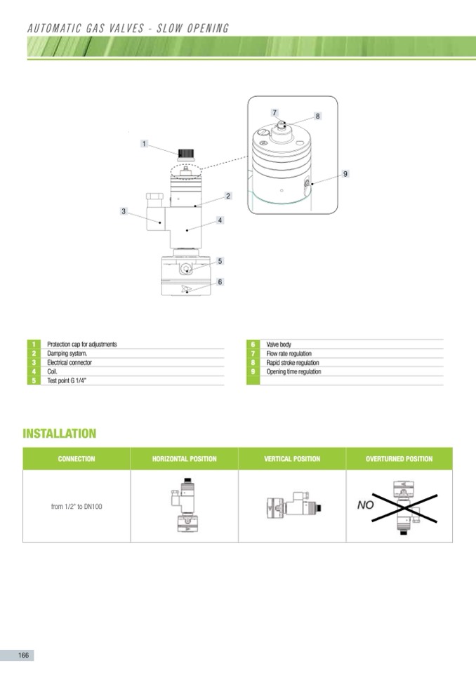
Protection cap for adjustments.
2
Damping system.
3
Electrical connector
4
Coil.
5
Test point G 1/4”.
6
Valve body.
7
Flow rate regulation.
8
Rapid stroke regulation.
9
Opening time regulation.
O
PENING
1
5-SO
2
3
2
4
5
6
230V
C1+
C 2-
e
n
sions:
=
1/2”
=
3/4”
=
1”
SO=Slow Opening
1
Protection cap for adjustments
2
Damping system.
3
Electrical connector
4
Coil.
5
Test point G 1/4”
Identification symbol of the “rectifier”
connectors. (see table coil marking)
D
ESCRIPTION
Clockwise
HorIzonTal posITIon
Clockwise
aUToMaTIC Gas vaLves - sLow openInG
INSTAllATION
and normally closed.
G
allow the regulation of:
connEcTIon
o
pen when the coil is powered and close
M
OVE THE DAMPING SYSTEM WITH
from 1/2” to DN100
I
ON VALVES
f
ore installation.
o
w facing towards the user appliance.
a
llow debris or scraps of metal to enter
o
t more then max pressure of the valve.
h
e coil voltage.
s
-tight after installation.
166
oVErTurnED posITIon
must be carried out only by qualified
English
1
3
9
6
7
8
9
Valve body
Flow rate regulation
Rapid stroke regulation
Opening time regulation
Counter clockwise
VErTIcal posITIon
Counter clockwise
7
8

