ING
O
ING
3
s:
SO=Slow Opening
C1+
O
SETTINGS
C 2-
230V
C1+
Identification symbol of the “rectifier”
connectors. (see table coil marking)
ING
3
230V
C 2-
C1+
s:
O
s:
SO=Slow Opening
3
SO=Slow Opening
Identification symbol of the “rectifier”
C
RIPTION
n
ormally closed.
w
the regulation of:
C
RIPTION
7
connectors. (see table coil marking)
Counter clockwise
w
hen the coil is powered and close
n
ormally closed.
w
the regulation of:
Counter clockwise
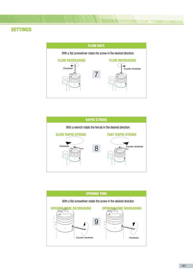
fasT rapID sTrokE
Counter clockwise
Counter clockwise
Clockwise
E
THE DAMPING SYSTEM WITH
C
RIPTION
w
hen the coil is powered and close
n
ormally closed.
w
the regulation of:
E
THE DAMPING SYSTEM WITH
VALVES
n
stallation.
rapID sTrokE
w
hen the coil is powered and close
c
ing towards the user appliance.
debris or scraps of metal to enter
E
THE DAMPING SYSTEM WITH
VALVES
n
stallation.
r
e then max pressure of the valve.
c
ing towards the user appliance.
i
l voltage.
debris or scraps of metal to enter
h
t after installation.
VALVES
n
stallation.
s
r
et tbhencmararxiepdroeusst uornelyobf ythqeuvalilfvied.
c
ing towards the user appliance.
i
l voltage.
debris or scraps of metal to enter
h
t after installation.
s
t be carried out only by qualified
r
e then max pressure of the valve.
i
l voltage.
h
t after installation.
s
t be carried out only by qualified
opEnInG TImE
flow raTE
flow DEcrEasInG
Clockwise
Clockwise
Clockwise
Clockwise
slow rapID sTrokE
Clockwise
8
Clockwise
With a flat screwdriver rotate the screw in the desired direction
connectors. (see table coil marking)
Withaflatscrewdriverrotatethescrewinthedesireddirection:
C2-
With a wrench rotate the ferrule in the desired direction:
opEnInG TImE DEcrEasInG
Counter clockwise
Counter clockwise
9
opEnInG TImE IncrEasInG
Clockwise
Clockwise
Counter clockwise
230V
flow IncrEasInG
Identification symbol of the “rectifier”
Counter clockwise
Counter clockwise
167

