sLaM shUT oFF vaLves – opso
CODE DESCRIPTION
INSTAllATION
The Slam shut off valves were designed for installation in any industrial gas
system.
The purpose of these valves is to block any excess gas flow and protect the
entire system.
1 SLAM SHUT OFF VALVE:
SV = Threaded connections
SVD=Flanged connections
2 DIMENSIONS:
025= 1”
25= DN25
032= 1 1/4”
32= DN32
040= 1 1/2”
40= DN40
050= 2”
50= DN50
65= DN65
80= DN80
100= DN100
PRE
Unscrew the regulation ca
The outlet pressure is regul
Using a 10mm Allen key tur
sure and anti-clockwise to r
After completing the regula
1
Regulation cap
3 bar:
-6B = 6bar
4 MAXIMUM PRESSURE
OPSO = 200 - 700mbar
DESCRIPTION
Slam shut off valve
SV015-6B-OPSO
1
2
3
4
Fig.1
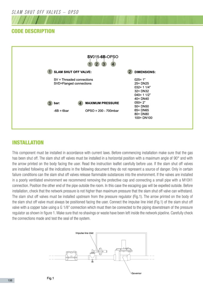
This component must be installed in accordance with current laws. Before commencing installation make sure that the gas
Whenthegasflowpressureexceedsthecalibrationpressurethevalvecloses
automatically and makes the plant safe.
has been shut off. The slam shut off valves must be installed in a horizontal position with a maximum angle of 90° and with
After the problem has been resolved rearm the valve. All the slam shut off
the arrow printed on thevablovdesy afarecinregartmhedusmear.nRuaelalyd. the instruction leaflet carefully before use. If the slam shut off valves
are installed following all the indications in the following document they do not represent a source of danger. Only in certain
Before installation, check that the network pressure is not higher than maximum
pressure that the slam shut off valve can withstand.
MARKINGS
failure conditions can the slam shut off valves release flammable substances into the environment. If the valves are installed
The Slam shut off valves all have a data plate with the main technical specifi-
v
alve
connection. Position the other end of the pipe outside theSrVo0o5m0.-6InBt-hOisPScaOse the escaping gas will be expelled outside. Before
D
The arrow printed on the 0b4o9dy7 of the slam shut off valve must always be posi-
installation, check that the network pressure is not higher than maximum pressure that the slam shut off valve can withstand.
e
If the slam shut off valves are installed following all the indications in the follow-
ing document they do not represent a source of danger.
Only in certain failure conditions can the slam shut off valves release flammable
substances into the environment. If the valves are installed in a poorly ventilated
environment we recommend removing the protective cap and connecting a
small pipe with a M10X1 connection. Position the other end of the pipe outside
GStoavbeilrinseor
the room. In this case the escaping gas will be expelled outside.
Fig.1
198
Carefully check the connections made and test the seal of the system.
This component must be installed in accordance with current laws. Before com-
mencing installation make sure that the gas has been shut off.
The slam shut off valves must be installed in a horizontal position with a maxi-
2
D
I
M
E
N
S
I
O
N
S
:
P
R
E
S
S
U
R
E
C
A
L
I
B
R
A
T
I
O
N
cations of the particular model (Fig.1):
in a poorly ventilated environment we recommend removing the protective cap and connecting a small pipe with a M10X1
English
The slam shut off valves must be installed upstream from the pressure regula-
tor (Fig.1).
Make sure the flow downstr
For models (1”, DN25, 1”1/
tioned facing the user.
for the flanged models (DN
UNI EN 88/2
Body: 2"
The slam shut off valves must be installed upstream from the pressure regulator (Fig.1). The arrow printed on the body of
Pe max: 6 bar
Class: A
Connect the impulse line inlet (Fig.1) of the slam shut off valve with a copper
theslamshutoffvalvemustalwaysbeposPitdio:n2e0d0 fac7i0n0gmthbaeruser.ConnGecrotuthpe:im2pulselineinlet(Fig.1)oftheslamshutoff
tube using a G 1/8” connection which must then be connected to the piping
T. amb.: -20 +60°C
valve with a copper tubedouwsninsgtreaaGm1o/f8t”hecopnrneescstuiorne rwehgiuchlatmour s(St thabenilisbercso) nanseschtoewd ntointhfiegupriepi1n.g downstream of the pressure
Fig.1
S/N 162137001
r e g u lator as shown in figure 1. Make sure that no shavings or waste have been left inside the network pipeline. Carefully check
Make sure that no shavings or waste have been left inside the network pipeline.
the connections made and test the seal of the systemI.NSTALLATION
Impulse line inlet
mum angle of 90° and with the arrow printed on the body facing the user.
Read the instruction leaflet carefully before use.
rearm handle
Fig.3a
We recommend checking
arise make sure that there
any work on it. All mainte
nel.
Make sure that no shavings
Carefully check the connec
Fig.2
Impulse
3
S
7
Protective

