downstream of the pressure regulator (Stabilisers) as shown in figure 1.
Make sure that no shavings or waste have been left inside the network pipeline.
Carefully check the connections made and test the seal of the system.
Impulse line inlet
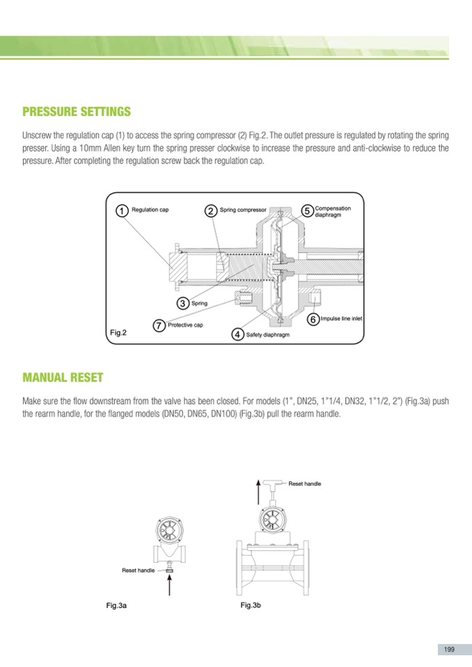
PRESSuRE SETTINGS
32= DN32
040= 1 1/2”
40= DN40
050= 2”
50= DN50
a
llation in a6n5y=inDdNus6t5rial gas
80= DN80
s
s gas flow1a0n0d= DprNo1te0c0t the
n
pressure the valve closes
v
alve. All the slam shut off
a
llation in any industrial gas
Fig.2
s
s gas flow and protect the
h
the main technical specifi-
n
pressure the valve closes
5
Compensation
diaphragm
6
Impulse line inlet
mANuAl RESET
3
Spring
Make sure the flow downstream from the valve has been closed.
v
alve. All the slam shut off
o
dy: 2"
6
Impulse line inlet
For models (1”, DNP2r5ot,e1ct”iv1e/4ca,pDN32, 1”1/2, 2”) (Fig.3a) push the rearm handle,
foFritgh.e2 flanged models (DN50, DN65, DN100) (Fig.3b) pull the rearm handle.
4
Safety diaphragm
MANUAL REARM
rearm handle
Make sure the flow downstream from the valve has been closed.
For models (1”, DN25, 1”1/4, DN32, 1”1/2, 2”) (Fig.3a) push the rearm handle,
for the flanged models (DN50, DN65, DN100) (Fig.3b) pull the rearm handle.
l
ass: A
Fig.1
2 DIMENSIONS:
PRESSURE CALIBRATION
025= 1”
Unscrew the regulation cap (1) to access the spring presser (2) Fig.2.
Unscrew the regulation cap (1) to access the spring compressor (2) Fig.2. The outlet pressure is regulated by rotating the spring
25= DN25
The outlet pressure is regulated by rotating the spring presser.
presser. Using a 10mm Allen key turn the spring presser clockwise to increase the pressure and anti-clockwise to reduce the
032= 1 1/4”
Using a 10mm Allen key turn the spring presser clockwise to increase the pres-
pres3s2u=reD.NA3ft2er completinsgFuitrghe.e1arnedgaunlatit-icolnocskcwreiswe btoacrekdtuhceertehgeuplaretisosnucrea.p.
After completing the regulation screw back the regulation cap.
PRESSURE CALIBRATION
040= 1 1/2”
40= DN40
2 DIMENSIONS:
050= 2”
50= DN50
Unscrew the regulation cap (1) to access the spring presser (2) Fig.2.
The outlet pressure is regulated by rotating the spring presser.
025= 1”
65= DN65
25= DN25
1
Regulation cap
2
Spring compressor
5
Compensation
Using a 10mm Allen key turn the spring presser clockwise to incrdeiaapshreagtmhe pres-
80= DN80
032= 1 1/4”
100= DN100
sure and anti-clockwise to reduce the pressure.
After completing the regulation screw back the regulation cap.
1
Regulation cap
2
Spring compressor
3
Spring
7
Protective cap
4
Safety diaphragm
7
MANUAL REARM
Make sure the flow downstream from the valve has been closed. For models (1”, DN25, 1”1/4, DN32, 1”1/2, 2”) (Fig.3a) push
the rearm handle, for the flanged models (DN50, DN65, DN100) (Fig.3b) pull the rearm handle.
r
oup : 2
h
the main technical specifi-
o
dy: 2"
t
h current laws. Before com-
l
ass: A
e
n shut off.
r
oup : 2
rReeasrmet handlle
i
z
ontal position with a maxi-
body facing the user.
t
he indications in the follow-
t
h current laws. Before com-
n
ger.
e
n shut off.
o
ff valves release flammable
i
z
ontal position with a maxi-
s
talled in a poorly ventilated
body facing the user.
t
ive cap and connecting a
t
her end of the pipe outside
e
lled outside.
rearm handle
Fig.3a
Fig.3b
MAINTENANCE
t
he indications in the follow-
n
ger.
o
ff valves release flammable
s
talled in a poorly ventilated
t
ive cap and connecting a
t
her end of the pipe outside
e
lled outside.
Rreasremt hanndlele
We recommend checking the action of the valve regularly. Should the need
arise make sure that there is no pressurised gas inside the valve before doing
any work on it. All maintenance work must be done by qualified person-
Fig.3b
MAINTENANCE
We recommend checking the action of the valve regularly. Should the need
arise make sure that there is no pressurised gas inside the valve before doing
any work on it. All maintenance work must be done by qualified person-
n
e
l
.
nel.
Fig.3a
Stabiliser
Stabiliser
199

