mod. 160
Portata termica 150,0 kW
Potenza termica utile (50°-30°C) 160,0 kW
Efficienza a Pmax (50°C-30°C) 106,8
mod. 220
Portata termica 207,0 kW
Potenza termica utile (50°C-30°C) 220,0 kW
Efficienza a Pmax (50°C-30°C) 106,8
mod. W 320
Portata termica 299,0 kW
Potenza termica utile (50°C-30°C) 320,0 kW
Efficienza a Pmax (50°C-30°C) 106,8
Il grande contenuto d’acqua della caldaia e la sua
estensione verticale assicurano ai generatori della serie
OPERA bassissime perdite di carico anche a portate elevate
e permette al generatore di lavorare con ΔT tra mandata e
ritorno praticamente libero, fino ad un massimo di 60°C a
portata prossima allo zero. Tutto ci
ò si traduce in una grande
flessibilità impiantistica, che svincola il progettista dai limiti
imposti dal tipo di generatore. Può inoltre essere collegata
direttamente all’impianto senza l’interposizione di organi
di separazione, anche nel caso di impianti a più zone,
solitamente caratterizzati da variazioni sensibili delle portate
e del Δt tra mandata e ritorno in caldaia.
1
mod. 160
Thermal capacity 150.0 kW
Useful thermal power (50°C-30°C) 160.0 kW
Efficiency at Pmax (50°C-30°C) 106.8
mod. 220
Thermal capacity 207.0 kW
Useful thermal power (50°C-30°C) 220.0 kW
Efficiency at Pmax (50°C-30°C) 106.8
mod. W 320
Thermal capacity 299.0 kW
Useful thermal power (50°C-30°C) 320.0 kW
Efficiency at Pmax (50°C-30°C) 106.8
The large water content of the boiler and its vertical
extension ensure the generators of the OPERA series
have very low pressure drops even at high flow rates and
allow the generator to work with ΔT between delivery and
return practically free, up to a maximum of 60°C close to
zero flow rate. All that translates into great engineering
flexibility, which frees the designer from the limits imposed
by the type of generator. It can also be connected
directly to the system without interposing separation
elements, even in the case of multi-zone systems, usually
characterised by significant variations in flow rates and Δt
between delivery and return to the boiler.
8
15
7
2
8
9
10
11
3
5
4
14
13
12
5
6
ATTACCHI IDRAULICI GAS E USCITE FUMI
GAS AND FLUE GAS OUTLET PLUMBING FITTINGS
MODELLO / MODEL
70
125
160
220
320
3
Uscita fumi Ø
Flue gas outlet Ø
80
100
160
160
200
11
Mandata impianto
System delivery
1” 1/4
1” 1/4
2”
2”
DN 65
13
Ritorno impianto
System return
1” 1/4
1” 1/4
2”
2”
DN 65
15
Ingresso gas
Gas inlet
3/4”
1”
1”
1”
1”
12
Scarico caldaia
Boiler drain
3/4”
3/4”
3/4”
3/4”
3/4”
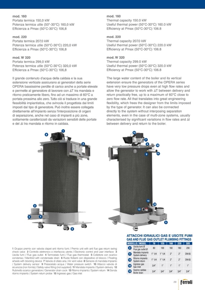
1 Gruppo premix con valvola clapet anti ritorno fumi / Premix unit with anti flue gas return swing
check valve 2 Controllo elettronico e interfaccia utente / Electronic control and user interface 3
Uscita fumi / Flue gas outlet 4 Termostato fumi / Flue gas thermostat 5 Collettore con scarico
condensa / Manifold with condensate drain 6 Ruote flottanti con dispositivo di blocco / Floating
wheels with blocking device 7 Valvola di sfiato aria / Air vent valve 8 Sensore di mandata impianto
/ System delivery sensor 9 Pressostato acqua / Water pressure switch 10 Attacco valvola di
sicurezza(nonfornita)/Safetyvalvefitting(notsupplied) 11Mandataimpianto/Systemdelivery 12
Rubinetto scarico generatore / Generator drain cock 13 Ritorno impianto / System return 14 Sonda
ritorno impianto / System return probe 15 Ingresso gas / Gas inlet
29

