TD
v
v
v
v
v
v
TA
v
v
v
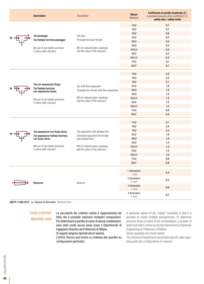
Tee passaggio
Tee filettata femmina passaggio
NB: per le tee ridotte sommare
il valore delle riduzioni
Tee con separazione
flusso
Tee filettata femmina
con separazione
flusso
NB: per le tee ridotte sommare
il valore delle riduzioni
Tee separazione con
flusso diviso
Tee separazione
filettata femmina
con
flusso diviso
NB: per le tee ridotte sommare
il valore delle riduzioni
Riduzione
v= Sezione di riferimento Reference flow
Tee duct
Threaded tee duct female
NB: for reduced pipe-couplings,
add the value of the reducers
Tee with
flow separation
Threaded tee female with
flow separation
NB: for reduced pipe-couplings,
add the value of the reducers
Tee separation with divided flow
Threaded separation tee female
with divided
flow
NB: for reduced pipe-couplings,
add the value of the reducers
Reducer
14x2
0,7
16x2
0,7
18x2
0,6
20x2
0,5
26x3
0,5
32x3
0,3
40x3,5
0,3
50x4
0,2
63x4,5
0,2
75x5
0,1
90x7
0,1
14x2
2,0
16x2
2,2
18x2
2,1
20x2
1,8
26x3
1,8
32x3
1,5
40x3,5
1,3
50x4
1,2
63x4,5
1,0
75x5
0,9
90x7
0,8
14x2
2,1
16x2
2,4
18x2
2,2
20x2
1,9
26x3
1,8
32x3
1,5
40x3,5
1,3
50x4
1,2
63x4,5
1,0
75x5
0,8
90x7
0,8
v
v
TG
48
v
v
v
UNI/TS 11589 2015
Misure
Coef
ficiente di perdita localizzata (
ξ )
Descrizione
Description
Measure
Localised pressure drop coef
ficient (
ξ )
safety-plus / safety-metal
Corpi collettori
Manifold units
v
La peculiarit
à dei collettori safety
è rappresentata dal
fatto che
è possibile realizzare molteplici composizioni.
Per determinare la perdita di carico di alcune combinazioni,
sono state svolte alcune prove preso il Dipartimento di
Ingegneria Idraulica del Politecnico di Milano.
Di seguito vengono riportati alcuni esempi.
L’Uf
ficio Tecnico può fornire su richiesta dati speci
fici su
configurazioni particolari.
A particular aspect of the “safety” manifolds is that it is
possible to create multiple arrangements. To determine
pressure drops of some of the combinations, a number of
tests have been carried out by the Department of Hydraulic
Engineering at Politecnico di Milano.
Some examples are shown below.
The Technical Department can provide speci
fic data regar-
ding particular con
figurations on request.
1 dimensione
1 size
2 dimensioni
2 sizes
3 dimensioni
3 sizes
4 dimensioni
4 sizes
0,4
0,5
0,6
0,7

