TacoTherm Dual ZEPTO
Functional description
3.5.2 Differential pressure control valve
The differential pressure control valve ensures there is a constant
differential pressure in the subsystem ( Ä Further information
on page 45).
Fig. 21: Differential pressure control
valve
3.5.3 Water hammer damper
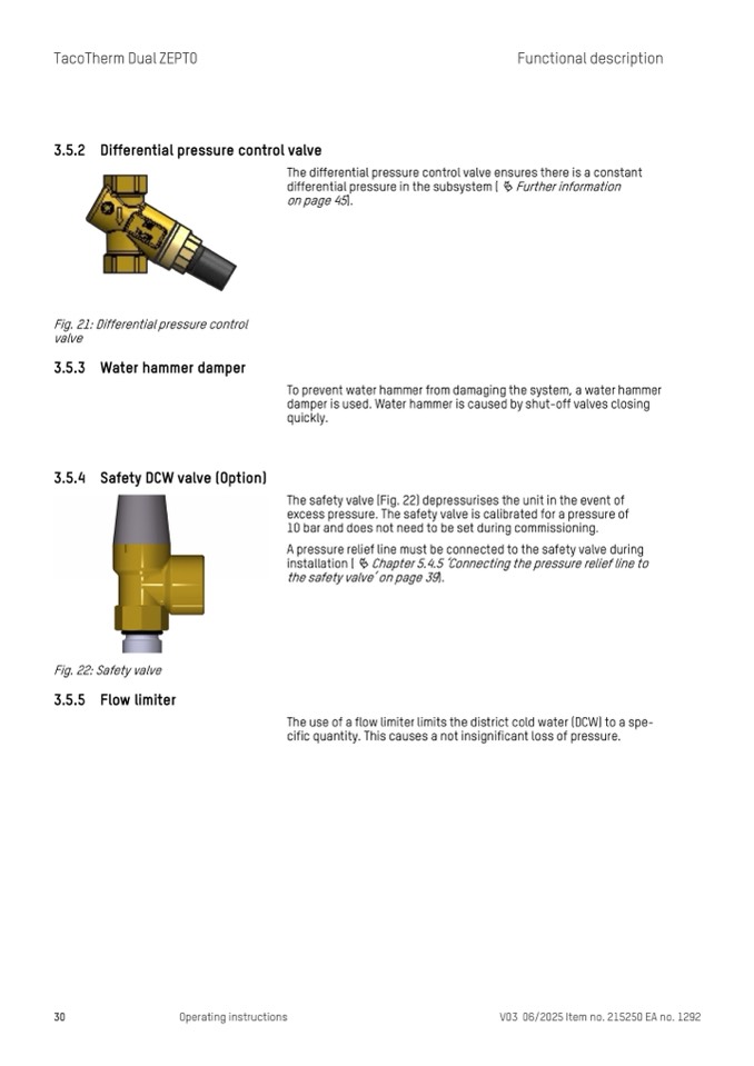
3.5.4 Safety DCW valve (Option)
Fig. 22: Safety valve
3.5.5 Flow limiter
To prevent water hammer from damaging the system, a water hammer
damper is used. Water hammer is caused by shut-off valves closing
quickly.
The safety valve (Fig. 22) depressurises the unit in the event of
excess pressure. The safety valve is calibrated for a pressure of
10 bar and does not need to be set during commissioning.
A pressure relief line must be connected to the safety valve during
installation (
Ä Chapter 5.4.5 ‘Connecting the pressure relief line to
the safety valve’ on page 39).
The use of a flow limiter limits the district cold water (DCW) to a spe-
cific quantity. This causes a not insignificant loss of pressure.
30
Operating instructions
V03 06/2025 Item no. 215250 EA no. 1292

