TacoTherm Dual ZEPTO
Assembly
Connecting the fix rail
Fitting the cover
6.
If a first fix rail has already been installed, connect the pipes.
7.
If the heat interface unit was supplied with a cover, hook the
cover onto the top of the base plate.
8.
Fasten the cover onto the base plate using 6 screws (2 on each
side and 2 on the underside).
5.
CAUTION!
Risk of injury due to airborne drilling dust and
chips!
Wear protective goggles.
Tighten the bolts to fasten the heat interface unit to the instal-
lation location.
5.4 Connecting pipes
5.4.1 Preparing the heat interface unit
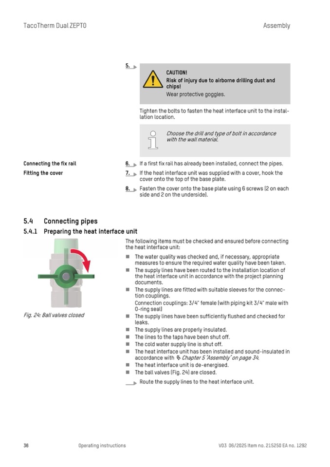
Fig. 24: Ball valves closed
n
n
n
n
n
n
n
n
n
n
The water quality was checked and, if necessary, appropriate
measures to ensure the required water quality have been taken.
The supply lines have been routed to the installation location of
the heat interface unit in accordance with the project planning
documents.
The supply lines are fitted with suitable sleeves for the connec-
tion couplings.
Connection couplings: 3/4" female (with piping kit 3/4" male with
O-ring seal)
The supply lines have been sufficiently flushed and checked for
leaks.
The supply lines are properly insulated.
The lines to the taps have been shut off.
The cold water supply line is shut off.
The heat interface unit has been installed and sound-insulated in
accordance with
Ä Chapter 5 ‘Assembly’ on page 34.
The heat interface unit is de-energised.
The ball valves (Fig. 24) are closed.
Route the supply lines to the heat interface unit.
The following items must be checked and ensured before connecting
the heat interface unit:
36
Operating instructions
V03 06/2025 Item no. 215250 EA no. 1292
Choose the drill and type of bolt in accordance
with the wall material.

