Final commissioning
TacoTherm Dual ZEPTO
8
Final commissioning
8.1 Setting the differential pressure control valve
Personnel:
n Heating and sanitary technician
1.
Determine the differential pressure using the data sheet
( Ä Chapter 1.2 ‘Other applicable documents’ on page 8).
2.
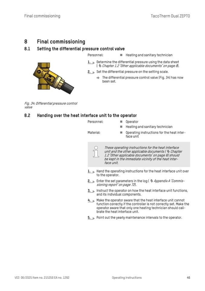
Set the differential pressure on the setting scale.
ð The differential pressure control valve (Fig. 34) has now
been set.
Fig. 34: Differential pressure control
valve
8.2 Handing over the heat interface unit to the operator
Personnel:
n Operator
n Heating and sanitary technician
Material:
n Operating instructions for the heat inter-
face unit
1.
Hand the operating instructions for the heat interface unit over
to the operator.
2.
Enter the set parameters in the log ( Ä Appendix A ‘Commis-
sioning report’ on page 72).
3.
Instruct the operator on how the heat interface unit functions,
and its individual components.
4.
Make the operator aware that the heat interface unit cannot
function correctly if the controller is not correctly set. Make the
operator aware that only one heating technician should cali-
brate the heat interface unit.
5.
Point out the yearly maintenance intervals to the operator.
These operating instructions for the heat interface
unit and the other applicable documents ( Ä Chapter
1.2 ‘Other applicable documents’ on page 8) should
be kept in the immediate vicinity of the heat inter-
face unit.
V03 06/2025 Item no. 215250 EA no. 1292
Operating instructions
45

