TacoTherm Dual ZEPTO
Installing and removing options
9
Installing and removing options
If options are replaced or subsequently installed, the
heat interface unit must be temporarily shut down
and the corresponding pipes drained.
– Ä Chapter 13.1 ‘Shutting down the heat inter-
face unit for a short period (<24 h)’ on page 60
– Ä Chapter 13.3 ‘Emptying the heat interface unit’
on page 61
Observe the applicable installation instructions in
respect of the installation of the options.
Removing the adaptor
Personnel:
n Heating and sanitary technician
Protective equipment: n Protective gloves
Tool:
n Adjustable spanner
Material:
n Cloth
1.
2.
3.
4.
5.
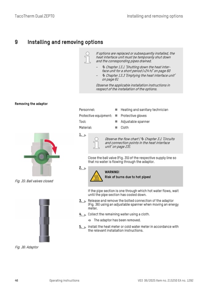
Close the ball valve (Fig. 35) of the respective supply line so
that no water is flowing through the adaptor.
Fig. 35: Ball valves closed
If the pipe section is one through which hot water flows, wait
until the pipe section has cooled down.
Release and remove the bolted connection of the adaptor
(Fig. 36) using an adjustable spanner when moving an energy
meter.
Collect the remaining water using a cloth.
ð The adaptor has been removed.
Install the heat meter or cold water meter in accordance with
the relevant installation instructions.
Fig. 36: Adaptor
46
Operating instructions
V03 06/2025 Item no. 215250 EA no. 1292
Observe the flow chart ( Ä Chapter 3.1 ‘Circuits
and connection points in the heat interface
unit’ on page 23).
WARNING!
Risk of burns due to hot pipes!

