Faults
TacoTherm Dual ZEPTO
2.
3.
Release the bolted connection for the pump using an adjust-
able spanner, and lift the pump off.
4.
Collect the remaining water using a cloth.
5.
Install the new pump.
6.
Ensure that new O-ring seals are available.
7.
Tighten the bolted connections using an adjustable spanner.
8.
Restart the heat interface unit (
Ä Chapter 7 ‘Preliminary com-
missioning’ on page 42 and
Ä Chapter 8 ‘Final commissioning’
on page 45).
9.
Set the pump in accordance with the controller instructions for
the unit (
Ä Chapter 1.2 ‘Other applicable documents’
on page 8).
WARNING!
Risk of burns due to hot pipes!
If the pipe section is one through which hot water flows, wait
until the pipe section has cooled down.
11.5
Replacing the backflow preventer
Personnel:
Protective equipment:
Tool:
Material:
n Heating and sanitary technician
n Protective gloves
n Adjustable spanner
n Spare parts
n Cloth
1.
2.
3.
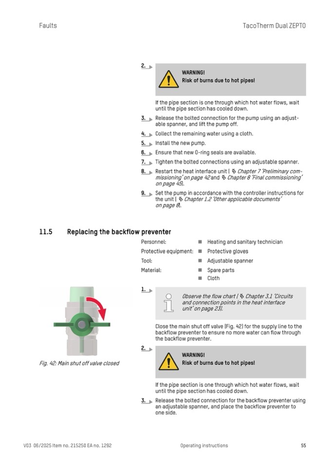
Close the main shut off valve (Fig. 42) for the supply line to the
backflow preventer to ensure no more water can flow through
the backflow preventer.
Observe the flow chart (
Ä Chapter 3.1 ‘Circuits
and connection points in the heat interface
unit’ on page 23).
Fig. 42: Main shut off valve closed
WARNING!
Risk of burns due to hot pipes!
If the pipe section is one through which hot water flows, wait
until the pipe section has cooled down.
Release the bolted connection for the backflow preventer using
an adjustable spanner, and place the backflow preventer to
one side.
V03 06/2025 Item no. 215250 EA no. 1292
Operating instructions
55

