TacoTherm Dual ZEPTO
Faults
11.3
Replacing the heat exchanger
Personnel:
Tool:
n Heating and sanitary technician
n Adjustable spanner
n Hexagon socket screw key
1.
Shut down the heat interface unit for a short period ( Ä Chapter
13.1 ‘Shutting down the heat interface unit for a short period
(<24 h)’ on page 60).
2.
Drain the heat interface unit ( Ä Chapter 13.3 ‘Emptying the
heat interface unit’ on page 61).
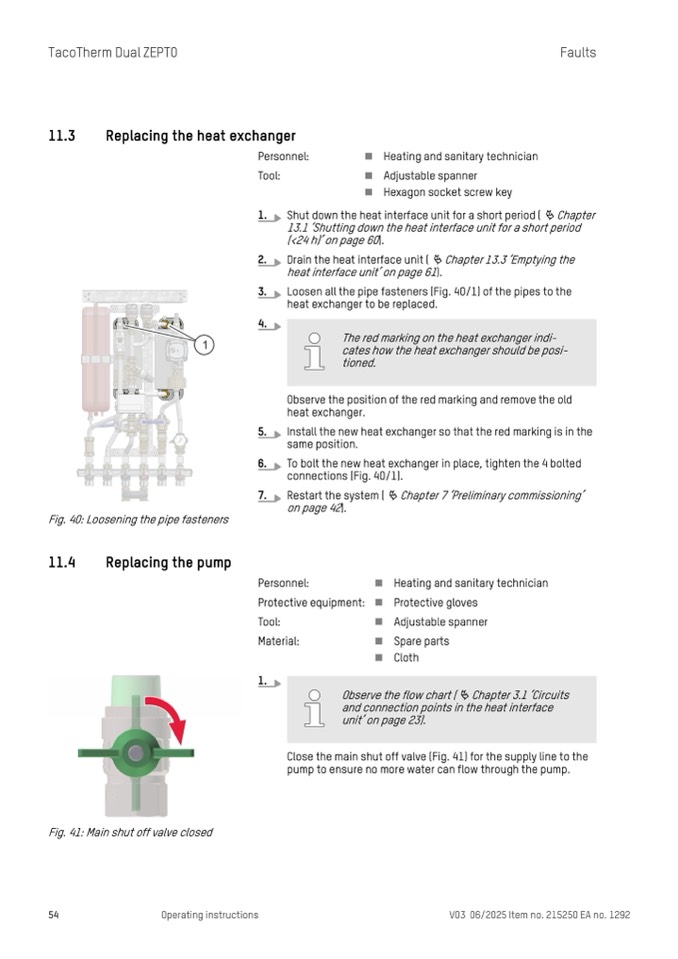
3.
Loosen all the pipe fasteners (Fig. 40/1) of the pipes to the
heat exchanger to be replaced.
4.
5.
Install the new heat exchanger so that the red marking is in the
same position.
6.
To bolt the new heat exchanger in place, tighten the 4 bolted
connections (Fig. 40/1).
7.
Restart the system (
Ä Chapter 7 ‘Preliminary commissioning’
on page 42).
Observe the position of the red marking and remove the old
heat exchanger.
Fig. 40: Loosening the pipe fasteners
11.4
Replacing the pump
1.
Fig. 41: Main shut off valve closed
54
Operating instructions
V03 06/2025 Item no. 215250 EA no. 1292
Personnel:
Protective equipment:
Tool:
Material:
n Heating and sanitary technician
n Protective gloves
n Adjustable spanner
n Spare parts
n Cloth
The red marking on the heat exchanger indi-
cates how the heat exchanger should be posi-
tioned.
Observe the flow chart ( Ä Chapter 3.1 ‘Circuits
and connection points in the heat interface
unit’ on page 23).
Close the main shut off valve (Fig. 41) for the supply line to the
pump to ensure no more water can flow through the pump.

