Terminali Idronici - Hydronic Terminals
VENTILCONVETTORI
FC E FCE BRUSHLESS
FC AND FCE BRUSHLESS FAN COILS
MADE IN ITALY
V
E
N
T
I
L
C
O
N
V
E
T
T
O
R
I
F
A
N
C
O
I
L
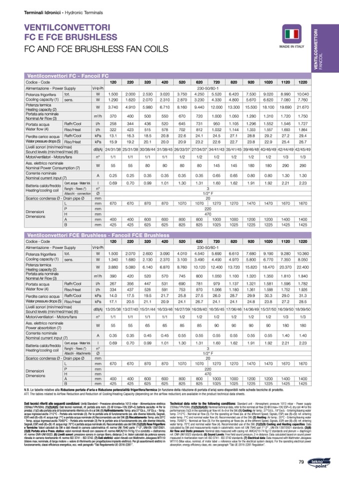
Ventilconvettori FC - Fancoil FC
Codice - Code
120
220
320
420
520
620
Alimentazione - Power Supply
230-50/60-1
720
820
920
1020
1120
1220
V-Hz-Ph
Potenza frigorifera
Cooling capacity (1)
Potenza termica
Heating capacity (2)
Portata aria nominale
Nominal Air Flow (3)
tot.
sens.
W
1.500
2.000
1.290
1.620
3.740
4.910
2.530
3.020
3.750
4.250
5.520
6.420
7.530
9.020
8.990
10.040
2.070
2.310
2.870
3.230
4.330
4.800
5.670
6.620
7.080
7.760
5.980
6.710
8.160
9.440
12.000 13.300 15.500 18.100 19.690 21.670
W
W
m
3
/h
370
400
500
550
258
344
436
520
322
423
515
578
13.1
16.3
18.5
20.8
15.9
19.2
20.1
20.0
670
720
1.000
645
731
950
702
812
1.032
22.6
24.1
24.5
20.9
23.2
22.6
1.050
1.280
1.310
1.720
1.750
1.105
1.296
1.552
1.546
1.727
1.144
1.333
1.557
1.693
1.864
27.1
28.8
29.2
27.2
29.4
22.7
23.8
22.9
25.4
26.7
Portata acqua
Water
flow (4)
Raffr/Cool
l/h
Perdite carico acqua
Water pressure drops (5)
Livelli sonori (min/med/max)
Sound levels (min/med/max) (6)
Risc/Heat
Risc/Heat
l/h
Raffr/Cool
kPa
kPa
dB(A)
24/31/38 25/31/38 30/38/44 31/38/45 26/33/37 27/34/37 34/41/43 35/41/45 39/46/48 40/46/49 42/44/49 42/45/49
1/1
1/1
1/1
1/1
1/2
1/2
1/2
1/2
1/2
1/2
1/3
1/3
55
55
80
80
80
80
145
145
180
180
290
290
Motori/ventilatori - Motors/fans
n°
Ass. elettrico nominale
Nominal Power Consumption (7)
Corrente nominale
Nominal current input (7)
Batteria caldo/freddo
Heating/cooling coil
W
A
0.25
0.25
0.35
0.35
0.69
0.70
0.99
1.01
670
670
870
870
400
400
600
600
425
425
625
625
0.35
0.35
1.30
1.31
1/2" F
20
1070
1070
1270
220
470
800
800
1000
825
825
1025
230-50/60-1
2.600
3.090
4.010
4.540
5.690
2.130
2.370
3.100
3.490
4.490
0.65
1.60
0.65
1.62
1270
1000
1025
0.80
0.80
1.91
1.92
1470
1470
1200
1200
1225
1225
1.30
1.30
2.21
2.23
1670
1670
1400
1400
1425
1425
9.280
10.360
7.350
8.050
Cont. acqua - Water Vol.
l
Ranghi - Rows (*)
n°
3
Attacchi - connection
Ø
Scarico condensa Ø - Drain pipe Ø
mm
L
mm
Dimensioni
Dimensions
P
mm
H
A
mm
mm
B
mm
Ventilconvettori FCE Brushless - Fancoil FCE Brushless
Codice - Code
120
220
320
420
520
620
720
820
920
1020
1120
1220
Alimentazione - Power Supply
V-Hz-Ph
Potenza frigorifera
Cooling capacity (1)
Potenza termica
Heating capacity (2)
Portata aria nominale
Nominal Air Flow (3)
tot.
sens.
W
W
W
m
3
/h
Portata acqua
Water
flow (4)
Raffr/Cool
l/h
Risc/Heat
l/h
Perdite carico acqua
Water pressure drops (5)
Raffr/Cool
kPa
Livelli sonori (min/med/max)
Sound levels (min/med/max) (6)
Risc/Heat
kPa
dB(A)
Motori/ventilatori - Motors/fans
n°
Ass. elettrico nominale
Power absorbition (7)
Corrente nominale
Nominal current input (7)
W
A
Batteria caldo/freddo
Heating/cooling coil
Cont. acqua - Water Vol.
l
Ranghi - Rows (*)
n°
Scarico condensa Ø - Drain pipe Ø
Dimensioni
Dimensions
Attacchi - Attachments
P
Ø
mm
L
mm
mm
H
mm
A
mm
B
mm
1.500
2.070
1.340
1.680
3.880
5.080
6.610
7.680
9.190
4.970
5.800
6.770
6.140
6.870
8.760
10.120 12.400 13.720 15.820 18.470 20.370 22.400
390
420
520
570
267
356
447
531
334
437
528
591
14.0
17.5
19.5
21.7
17.1
20.5
21.1
20.9
745
800
1.050
690
781
979
753
870
1.066
25.8
27.5
26.0
24.1
26.7
24.1
1.100
1.320
1.350
1.810
1.840
1.137
1.321
1.581
1.596
1.782
1.180
1.361
1.588
1.752
1.926
28.7
29.9
30.3
29.0
31.3
24.1
24.8
23.8
27.2
28.5
13/25/38 13/27/40 15/31/44 16/33/46 16/27/39 16/28/40 16/35/45 17/36/46 14/36/49 15/37/50 16/39/50 18/39/50
1/1
1/1
1/1
1/1
1/2
1/2
1/2
1/2
1/2
1/2
1/3
1/3
55
55
65
65
85
85
90
90
90
90
180
180
0.35
0.35
0.45
0.45
0.69
0.70
0.99
1.01
670
670
870
870
400
400
600
600
425
425
625
625
0.55
0.55
1.30
1.31
1/2" F
20
220
470
3
0.55
1.60
0.55
0.55
1.62
1.91
1270
1470
1000
1200
1025
1225
0.55
1.40
1.40
1.92
2.21
2.23
1470
1670
1670
1200
1400
1400
1225
1425
1425
1070
1070
800
800
825
825
1270
1000
1025
N.B. Le tabelle relative alla Riduzione portata d'aria e Riduzione potenzialità frigorifera/termica (in funzione della riduzione di portata d'aria) sono disponibili nelle schede tecniche di prodotto.
ATT. The tables related to Airflow Reduction and Reduction of Cooling/Heating Capacity (depending on the airflow reduction) are available in the product technical data sheets.
Dati tecnici riferiti alle seguenti condizioni: Unità Standard - Pressione atmosferica 1013 mbar - Alimentazione elettrica
230Vac/1Ph/50Hz. (1)(2)(4)(5): Dati tecnici nominali, rif. portata aria nom. (3) @ V.max=10V, ESP=0, batteria asciutta Per le
prestaz. (1)(2) alla portata aria di funzionamento riferirsi a 8+9 o al SW. (1) Raffreddamento: Temp. aria 27°Cb.s., 19°Cb.u. - Temp.
acqua ingresso/uscita 7/12°C - Portata aria nominale (3). Per le portate aria di funzionamento (es. alle diverse Velocità, Segnali,
ESP) vedi (8)+(9): rif. acqua ingr. 7°C e portata acqua nominale (4) Raccomandato uso del SW. (2) Riscaldamento: Temp. aria 20°C
- Temp. acqua ingresso/uscita 70/60°C - Portata aria nominale (3) Per le portate aria di funzionamento (es. alle diverse Velocit
à,
Segnali, ESP) vedi (8)+(9): rif. acqua ingr. 70°C e portata acqua nominale (4). Raccomandato uso del SW. (1)(2)(9) Rese Frigorifere
e Termiche: Valori calcolati da SW e dati rilevati in camera calorimetrica rif. norme UNI 7940 parte 1°-2°, UNI-EN 1397/2001.
(3)(8) Portata aria e Press. statica: valori nominali rilevati con cassone rif. norme AMCA210-74 fig.12 e condotto + diaframma
rif. norme CNR-UNI10023. (6) Livelli sonori: pressione sonora in campo libero, distanza 2 m. Valori calcolati da potenza sonora
rilevata in camera riverberante rif. norme ISO 3741 - ISO 3742. (7) Dati elettrici: valori rilevati con Wattmetro Jokogawa WT110
(Valore max, nominale, di targa motore = valore di riferimento per progettazione impianto elettrico). Per gli assorbimenti elettrici in
funzionamento, classi ef
ficienza energetica, ecc. vedi paragrafo “Tab Regolamento UE-2016-2281”.
Technical data refer to the following conditions: Standard unit - Atmospheric pressure 1013 mbar - Power supply
230Vac/1Ph/50Hz. (1)(2)(3)(4)(5): Nominal technical data, refer to the nominal air flow (3) @ V.max=10V, ESP=0, dry coil For the
performances (1)(2) in the operating air flow ref. 8+9 or the SW. (1) Cooling: Air temp.: 27°Cd.b., 19°Cw.b. - Entering/leaving water
temp. 7/12°C - Nominal air
flow (3). For the operating air flows (ex. at the different Speed, Signals, ESP) see (8)+(9): ref. entering
water temp. 7°C and nominal water flow (4). Recommended use of the SW. (2) Heating: Air temp.: 20°C - Entering/leaving water
temp. 70/60°C - Nominal air flow (3). For the operating air flows (ex. at the different Speed, Signals, ESP) see (8)+(9): ref. entering
water temp. 70°C and nominal water flow (4). Recommended use of the SW. (1)(2)(9) Cooling and Heating capacities: Data
calculated by SW and measurements made in calorimetric room ref. UNI 7940 part 1°-2° , UNI-EN 1397/2001 standards. (3)(8)
Air
flow and Static pressure: Nominal data measured with casing ref. AMCA210-74 fig.12 standards and plenum + diaphragm
ref. CNR-UNI10023 standards. (6) Sound Levels: Free field sound pressure, 2 m distance. Data calculated based on sound power
measured in riverberation room ref. ISO 3741 - ISO 3742 standards. (7) Electrical data: Data measured with Wattmeter Jokogawa
WT110 (Max value, nominal, of motor label = reference value for the electrical system design). For the operating electrical power
absorption, energy efficiency class, etc. see paragraph "Tab UE-2016-2281 Regulation”.
79

