TACOCONTROL Z1 S
Overview
Sensors
The sensors send the current values to the controller. The sensors
are plugged into the terminal block.
Provision is made for the following sensors:
n Fresh water flow rate sensor
n Domestic hot water temperature sensor
n Heating supply temperature sensor
n Storage water temperature sensor
3.3 Components of the controller
Controller box
Fig. 4: Controller box
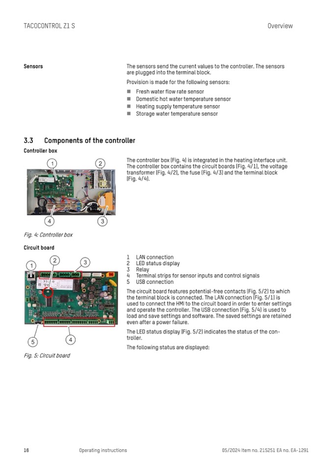
Circuit board
The controller box (Fig. 4) is integrated in the heating interface unit.
The controller box contains the circuit boards (Fig. 4/1), the voltage
transformer (Fig. 4/2), the fuse (Fig. 4/3) and the terminal block
(Fig. 4/4).
1 LAN connection
2 LED status display
3 Relay
4 Terminal strips for sensor inputs and control signals
5 USB connection
The circuit board features potential-free contacts (Fig. 5/2) to which
the terminal block is connected. The LAN connection (Fig. 5/1) is
used to connect the HMI to the circuit board in order to enter settings
and operate the controller. The USB connection (Fig. 5/4) is used to
load and save settings and software. The saved settings are retained
even after a power failure.
The LED status display (Fig. 5/2) indicates the status of the con-
troller.
The following status are displayed:
Fig. 5: Circuit board
16
Operating instructions
05/2024 Item no. 215251 EA no. EA-1291

