TACOCONTROL Z1 S
Commissioning and operation
6
Commissioning and operation
When commissioning, the parameters have already been set at
the factory (
Ä Chapter 7 ‘Parameter settings and display values’
on page 26) and can be changed on the HMI ( Ä Chapter 6.2.1
‘Setting parameters on the HMI’ on page 24).
NOTICE!
Damage to the pump due to dry operation!
The controller is a component of the heat interface
unit. The controller and the heat interface unit draw
energy from the same connector. If the controller is
connected to the mains power before filling the heat
interface unit, then the pumps operate dry and will
be damaged.
– Fill the heat interface unit before connecting the
controller to the mains power.
6.1 Connecting the HMI
Personnel:
n Operator
n Heating and sanitary technician
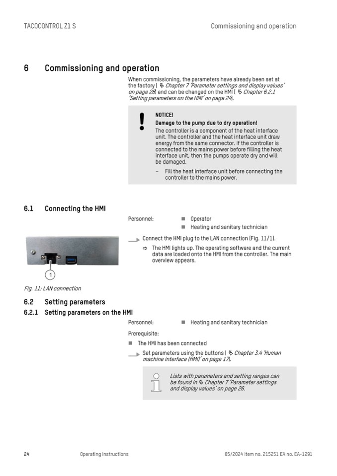
Connect the HMI plug to the LAN connection (Fig. 11/1).
ð The HMI lights up. The operating software and the current
data are loaded onto the HMI from the controller. The main
overview appears.
Fig. 11: LAN connection
6.2
6.2.1
Setting parameters
Setting parameters on the HMI
Personnel:
n Heating and sanitary technician
Prerequisite:
n The HMI has been connected
Set parameters using the buttons (
Ä Chapter 3.4 ‘Human
machine interface (HMI)’ on page 17).
24
Operating instructions
05/2024 Item no. 215251 EA no. EA-1291
Lists with parameters and setting ranges can
be found in
Ä Chapter 7 ‘Parameter settings
and display values’ on page 26.

