KESSEL AG
Catalogue EN 4.1
3.2 Pumping stations 137
3 Calculate the height of
the system chamber (D)
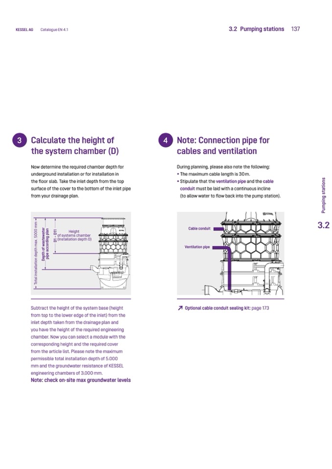
Now determine the required chamber depth for
underground installation or for installation in
the floor slab. Take the inlet depth from the top
surface of the cover to the bottom of the inlet pipe
from your drainage plan.
Height
of systems chamber
(Installation depth D)
Subtract the height of the system base (height
from top to the lower edge of the inlet) from the
inlet depth taken from the drainage plan and
you have the height of the required engineering
chamber. Now you can select a module with the
corresponding height and the required cover
from the article list. Please note the maximum
permissible total installation depth of 5.000
mm and the groundwater resistance of KESSEL
engineering chambers of 3.000 mm.
Note: check on-site max groundwater levels
4 Note: Connection pipe for
cables and ventilation
During planning, please also note the following:
• The maximum cable length is 30 m.
• Stipulate that the ventilation pipe and the cable
conduit must be laid with a continuous incline
(to allow water to flow back into the pump station).
Cable conduit
Ventilation pipe
↗
Optional cable conduit sealing kit: page 173
3.2
T
o
t
a
l
i
n
s
t
a
l
l
a
t
i
o
n
d
e
p
t
h
m
a
x
.
5
0
0
0
m
m
D
e
p
t
h
o
f
w
a
s
t
e
w
a
t
e
r
p
i
p
e
a
c
c
o
r
d
i
n
g
p
l
a
n
D
1
–
D
1
1
P
u
m
p
i
n
g
s
t
a
t
i
o
n
s

