Instructions for Laying
FSR 8.70.01
FLEXWELL Safety Pipe
Instructions for laying and mounting FLEXWELL Safety piping
FSR DN 12 – DN 150
Please note:
Please read these instructions through before be-
ginning with the laying of the piping and installing
the connection pieces. The instructions apply to the
laying of FLEXWELL Safety Pipe.
Familiarise yourself with the installation instructions for:
– FSR connection pieces with GRAPA or
elastomer seal
– FSR through connections
– FSR elbows and t-connectors
!
!
!
Important, temperature declaration:
All FSR pipes must be layed at temperatures above
0 °C to rule out damaging the PE layer.
Important, please take note:
The figures given in “bar” apply to the pressure in
excess of standard atmospheric pressure.
All FSR connections described in our instructions
for laying the pipes are intended for installation in
covered manholes, filling shafts, petrol pump shafts
or above ground level or in the shafts.
If it proves necessary to make connections in the
ground, please inform your planning engineer and
sales dealer beforehand.
gradient should be at least 1 – 2 %. Make sure that there
are no stones or pebbles in the sand bedding (sand grain
size < 2 mm). There should be 100 mm of stone-free sand
underneath the piping. At the end of laying the pipes, they
should be covered (once again with stone-free sand) all
around (min. 200 mm backfill). The pipes shall, including
bearing layer, have at least 300 mm total coverage.
For pipes under driving surfaces the laying depth must
be adapted to ground pressure requirements.
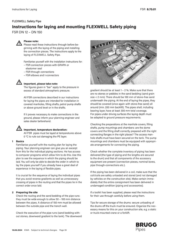
Checking the preparations at the manhole covers, filling
shafts, pump mountings and chambers: are the dome
covers and the filling shaft correctly prepared with the right
connecting flanges in the right places? The access man-
hole shafts must have been secured on the tank. The pump
mountings and chambers must be equipped with appropri-
ate arrangements for connecting the piping.
Check whether the complete inventory of piping has been
delivered (the type of piping and the lengths are secured
to the drum) and that all components of the accessory
equipment are present (connection pieces, nominal bores,
pipe through-connections etc.).
If the piping has been delivered in a coil, make sure that the
coil/coils are safely unloaded and stored (and not damaged
by vehicles on the construction site). Make certain imme-
diately that the entire consignment has been delivered in
undamaged condition (piping and accessories).
If a toolkit has been supplied, please read the instructions
for their use through carefully before using them.
Tips for secure storage of the drums: secure unloading of
the drums off the truck must be ensured. Organize the nec-
essary means for this on your construction site, e.g. a static
or truck-mounted crane or a forklift.
1 Basics
Familiarise yourself with the routing plan for laying the
piping. Your planning engineer can give you an excerpt
from this for the individual piping sections. He has access
to computer programs which allow him to do this. Use this
plan to see the sequence in which the piping should be
laid. You will only be able to decide the order in which to
lay the pipes yourself if you already have a great deal of
experience in the laying of flexible pipes.
It is crucial for the sequence of laying the individual pipes
that you avoid reverse gradients as well as unnecessary
crossing of pipes in the routing and that the pipes lie in the
correct order once laid.
2 Preparing the site
Check the routing and the sand bedding of the pipe runs:
they must be wide enough to allow 50 – 100 mm distance
between the pipes. A distance of 150 mm must be allowed
between the outside pipe and the trench wall.
Check the execution of the pipe runs (sand bedding with-
out stones, downward gradient to the tank). The downward
19.08.2024 KIWA Subject to technical changes. Page 39

