1.4
PUNTO DI LAVORO
L’energia che un ventilatore riceve dal motore elettrico viene
trasferita al fluido che l’attraversa sotto forma di pressione
totale (pt). La pressione totale che un ventilatore può fornire
non è però costante, ma varia in funzione della portata se-
condo la curva caratteristica del ventilatore. Anche la potenza
assorbita varia in funzione della portata.
Volendo far circolare una determinata quantità d’aria in un
impianto occorre fornire al fluido una certa energia, sotto
forma di pressione, per poter vincere gli attriti che questo
incontra nel moto.
Un ventilatore, installato in impianto, fornirà una portata cor-
rispondente al valore della pressione statica necessaria per
vincere la resistenza la moto del fluido nel circuito.
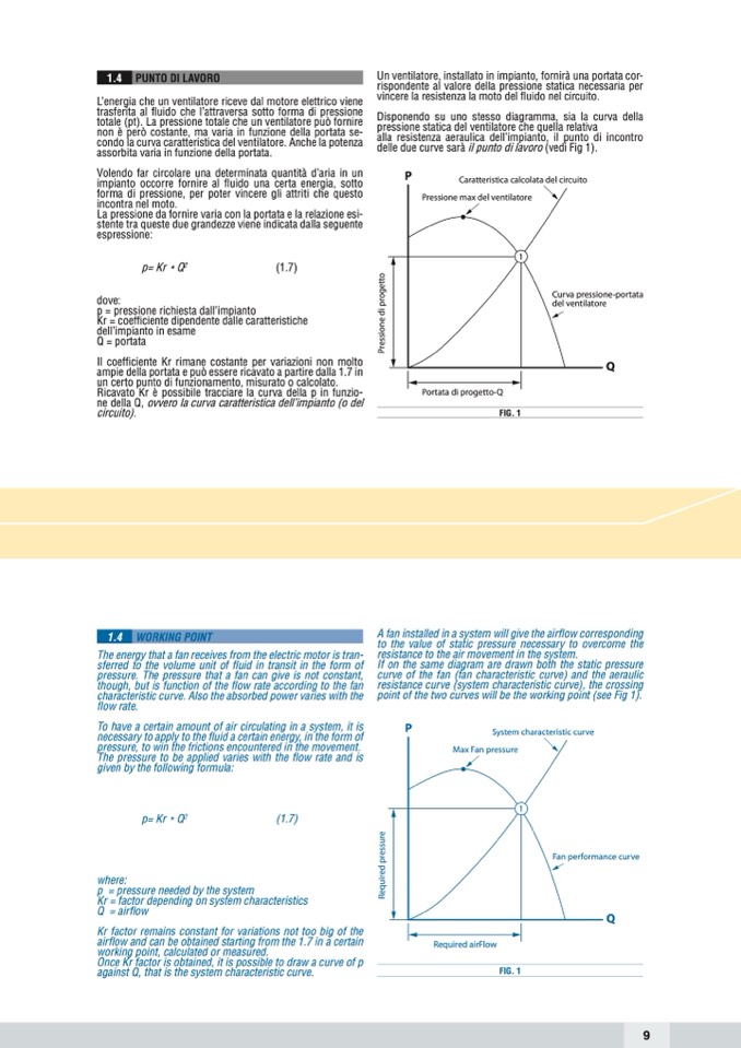
Disponendo su uno stesso diagramma, sia la curva della
pressione statica del ventilatore che quella relativa
alla resistenza aeraulica dell’impianto, il punto di incontro
delle due curve sarà il punto di lavoro (vedi Fig 1).
P
La pressione da fornire varia con la portata e la relazione esi-
stente tra queste due grandezze viene indicata dalla seguente
espressione:
Caratteristica calcolata del circuito
Pressione max del ventilatore
1
p= Kr * Q
2
(1.7)
dove:
p = pressione richiesta dall’impianto
Kr = coefficiente dipendente dalle caratteristiche
dell’impianto in esame
Q = portata
Il coefficiente Kr rimane costante per variazioni non molto
ampie della portata e può essere ricavato a partire dalla 1.7 in
un certo punto di funzionamento, misurato o calcolato.
Ricavato Kr è possibile tracciare la curva della p in funzio-
ne della Q, ovvero la curva caratteristica dell’impianto (o del
circuito).
Curva pressione-portata
del ventilatore
Q
Portata di progetto-Q
FIG. 1
1.4
WORKING POINT
The energy that a fan receives from the electric motor is tran-
sferred to the volume unit of fluid in transit in the form of
pressure. The pressure that a fan can give is not constant,
though, but is function of the flow rate according to the fan
characteristic curve. Also the absorbed power varies with the
flow rate.
To have a certain amount of air circulating in a system, it is
necessary to apply to the fluid a certain energy, in the form of
pressure, to win the frictions encountered in the movement.
The pressure to be applied varies with the flow rate and is
given by the following formula:
A fan installed in a system will give the airflow corresponding
to the value of static pressure necessary to overcome the
resistance to the air movement in the system.
If on the same diagram are drawn both the static pressure
curve of the fan (fan characteristic curve) and the aeraulic
resistance curve (system characteristic curve), the crossing
point of the two curves will be the working point (see Fig 1).
P
System characteristic curve
Max Fan pressure
1
FIG. 1
p= Kr * Q
2
(1.7)
where:
p = pressure needed by the system
Kr = factor depending on system characteristics
Q = airflow
Kr factor remains constant for variations not too big of the
airflow and can be obtained starting from the 1.7 in a certain
working point, calculated or measured.
Once Kr factor is obtained, it is possible to draw a curve of p
against Q, that is the system characteristic curve.
Fan performance curve
Q
Required airFlow
9
R
e
q
u
i
r
e
d
p
r
e
s
s
u
r
e
P
r
e
s
s
i
o
n
e
d
i
p
r
o
g
e
t
t
o

